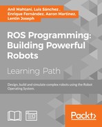
As we have four motors, we will connect the motors from the same side of the platform to the same output. We will connect digital signals to the L298N board to control the motors' behavior.
Each channel needs three signals to be controlled. IN1 and IN2 are digital signals used to set the rotation sense of the motor. ENA is used to control the intensity of the motor using Arduino Pulse Width Modulation (PWM) signal. This signal will control the left motor. For the right motor, IN3, IN4, and ENB will be the control signals. In the figure mentioned earlier, you have a diagram of the connection. Be careful connecting the wires from Arduino to L298N and programming INx signals. Once you have connected the motors to the L298N motor controller and the control signals to Arduino.
We can start a program to control the motors; you can find the entire code in chapter8_tutorials/src/robot_motors.ino. We are going to use Arduino IDE to code the sketch. First, we are going to declare the dependencies and define the Arduino pins connected to the L298N motor controller:
#include <ros.h>
#include <std_msgs/Int16.h>

#define ENA 6
#define ENB 11
#define IN1 8
#define IN2 9
#define IN3 12
#define IN4 13
Then, we are going to declare two callback functions to activate each motor. When a command message for the left wheel is received, the direction of the motors is set depending of the sign of the command. Digital signals IN1 and IN2 set the motor direction forward or backward. ENA is a PWM signal that controls the motor voltage; this signal is able to regulate the speed of the motor. The callback for the right wheel command is similar to the first callback:
void cmdLeftWheelCB( const std_msgs::Int16& msg)
{
  if(msg.data >= 0)
  {
    analogWrite(ENA,msg.data);
    digitalWrite(IN1, LOW);
    digitalWrite(IN2, HIGH);
  }
  else
  {
    analogWrite(ENA,-msg.data);
    digitalWrite(IN1, HIGH);
    digitalWrite(IN2, LOW);
  }
}

void cmdRightWheelCB( const std_msgs::Int16& msg)
{
  if(msg.data >= 0)
    {
    analogWrite(ENB,msg.data);
    digitalWrite(IN3, LOW);
    digitalWrite(IN4, HIGH);
  }
  else
  {
    analogWrite(ENB,-msg.data);
    digitalWrite(IN3, HIGH);
    digitalWrite(IN4, LOW);
  }
}
Then, two subscribers are declared, the topics are named cmd_left_wheel, we are using std::msgs::Int16 topic type, and we have just seen the callback functions:
ros::Subscriber<std_msgs::Int16> subCmdLeft("cmd_left_wheel",
 cmdLeftWheelCB );ros::Subscriber<std_msgs::Int16>
 subCmdRight("cmd_right_wheel",cmdRightWheelCB );
In the Arduino setup() function, the pins are declared as outputs and nh node is initialized and subscription to the topics starts:
void setup() {
  // put your setup code here, to run once:
  pinMode(ENA, OUTPUT);
  pinMode(ENB, OUTPUT);
  pinMode(IN1, OUTPUT);
  pinMode(IN2, OUTPUT);
  pinMode(IN3, OUTPUT);
  pinMode(IN4, OUTPUT);
  analogWrite(ENA,0);
  analogWrite(ENB, 0);
  digitalWrite(IN1, LOW);
  digitalWrite(IN2, HIGH);
  digitalWrite(IN3, LOW);
  digitalWrite(IN4, HIGH);

  nh.initNode();
  nh.subscribe(subCmdRight);
  nh.subscribe(subCmdLeft);
}
The loop function is as follows:
void loop()
{
  nh.spinOnce();
}
You can upload now the code to the board, and run the Arduino node from terminal:
    $ roscore
    $ rosrun rosserial_python serial_node.py /dev/ttyACM0
In other terminal, you can publish manually some commands to the left and the
right motor:
    $ rostopic pub /cmd_right_wheel std_msgs/Int16 "data: 190"
    $ rostopic pub /cmd_left_wheel std_msgs/Int16 "data: -100"
The command signals are expected to be between -255 and 255, and motors should stop with a zero value.
Now that we have our robot motor connected to ROS, it is time to control them with a joystick. We can unify the velocity topics, using differential drive kinematics equations and ROS geometry_msgs::Twist topic. By this way, we can send a standard message to the odometry nodes that is independent of the type of robot that we are using. As we have prepared c8_teleop_joy node to send this type of topics, we will be able to control the wheels with the joystick.
We are going to create a new sketch name robot_motors_with_twist.ino. We are going to copy the previous sketch, and we will have to add a new include at the beginning of the sketch to use geometry_msgs::Twist:
#include <geometry_msgs/Twist.h>
float L = 0.1; //distance between wheels
Then, we will include a new subscriber and its callback function:
void cmdVelCB( const geometry_msgs::Twist& twist)
{
  int gain = 4000;
  float left_wheel_data = gain*(twist.linear.x -
   twist.angular.z*L);  float right_wheel_data = gain*(twist.linear.x +
   twist.angular.z*L);
  {
    analogWrite(ENA,abs(left_wheel_data));
    digitalWrite(IN1, LOW);
    digitalWrite(IN2, HIGH);
  }
  else
  {
    analogWrite(ENA,abs(left_wheel_data));
    digitalWrite(IN1, HIGH);
    digitalWrite(IN2, LOW);
  }
  if(right_wheel_data >= 0)
  {
    analogWrite(ENB,abs(left_wheel_data));
    digitalWrite(IN3, LOW);
    digitalWrite(IN4, HIGH);
  }
  else
  {
    analogWrite(ENB,abs(left_wheel_data));
    digitalWrite(IN3, HIGH);
    digitalWrite(IN4, LOW);
  }
}
ros::Subscriber<geometry_msgs::Twist> subCmdVel("cmd_vel",
 cmdVelCB);
Now, you can upload the code to the Arduino board. In order to make easier to run all the nodes, we are going to create a launch file that manages the joystick, the robot model in the RViz visualizer, and the Arduino node.
You can launch the example with the following command in terminals:
    $ roslaunch chapter8_tutorials chapter8_tutorials robot_model_with_motors.launch
    $ rosrun rosserial_python serial_node.py /dev/ttyACM0
Now, you can control the robot with the joystick; also you can see in the RViz visualizer the robot model moving. If you are testing the code on an embedded ARM computer without display, you can comment the rviz node in the launch file.