3.3. TRANSFER-FUNCTION AND STATE-VARIABLE REPRESENTATION OF TYPICAL MECHANICAL CONTROL-SYSTEM DEVICES
Mechanical control-system devices can generally be classified as being either translational or rotational. The major difference between the two is that we talk of forces and translational units in the former, and torque and angular units in the latter. Newton’s three laws of motion [3] govern the action of both types of mechanical systems. Basically, these laws state that the sum of the applied forces, or torques, must equal the sum of the reactive forces, or torques, for a body whose acceleration is zero. Another way of stating this is that the sum of the forces must equal zero for a body at rest or moving at a constant velocity. We shall consider some representative translational systems and then some rotational systems. The basic concepts illustrated and developed here should be sufficient to enable the reader to handle more complex systems.
A. Mechanical Translation Systems
The three basic characteristics of a mechanical translational system are mass, stiffness, and damping. Mass represents an element having inertia. Stiffness represents the restoring force action such as that of a spring. Damping, or viscous friction, represents a characteristic of an element that absorbs energy. The symbols for the various quantities used in our analyses are shown in Table 3.1.
1. Force Applied to a Mechanical System Containing a Mass, Spring, and Damper. The case of a force f(t) applied to a mass, spring, and damper is shown in Figure 3.3. The system produces a displacement of the mass y(t) measured from a reference terminal y0, which is assumed to be stationary. The application of Newton’s law to this system yields
This second-order differential equation can be written as two first-order differential equations by defining
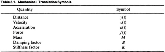
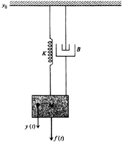
Figure 3.3 Force applied to a system containing a spring, a mass, and a damper.
The resulting state equations are given by
In phase-variable canonical form, these equations become
where

Assuming the system is initially at rest, the transfer function of this mechanical translation system, defined as the ratio of the output Y(s) divided by the input F(s), is readily found to be
and its simple block diagram appears in Figure 3.4.
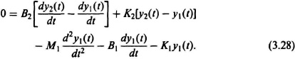
2. Force Applied to a Complex Mechanical System. Consider next the complex mechanical system illustrated in Figure 3.5. A force f(t) is applied to a mass, spring, and damper, which in turn applies a force to another mass, spring, and damper. Mass M2 is displaced a distance y2(t), and mass M1 is displaced a distance y1(t) with reference to y0. In order to apply Newton’s laws to this system, it is advantageous to first separate the mechanical system into a set of free-body diagrams as illustrated in Figure 3.6. Newton’s equations for this resulting system are

Figure 3.4 Block diagram for the spring-mass-damper system.

Figure 3.5 A mechanical system.
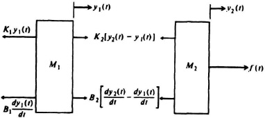
Figure 3.6 Free-body diagram for the system illustrated in Figure 3.5.
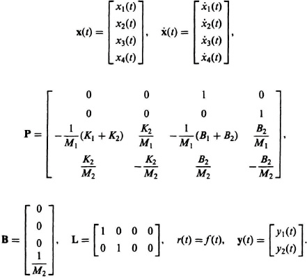
These two second-order differential equations can be transformed into four first-order differential equations by defining
The resulting state equations are given by

In phase-variable canonical form, these equations become
where
B. Mechanical Rotational Systems
The three basic characteristics of a mechanical rotational system are moment of inertia, stiffness, and damping. Rotational systems are quite similar to translational systems, except that torque equations are used to describe system equilibrium instead of force equations, and we use angular displacement, velocity, and acceleration quantities. The symbols for the various quantities used in our analysis are shown in Table 3.2.
Either the English set of units or the International System of units can be used for solution to the resulting equations. The primary thing to remember is to be consistent. Table 3.3 provides the conversion factors in going from the International System to the English set of units.
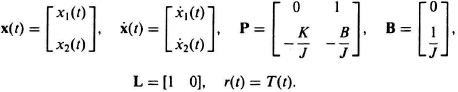
1. Torque Applied to a Body Having a Moment of Inertia, a Twisting Shaft, and a Damping Device. The configuration of a torque T(t) applied to a body having a moment of inertia J, a twisting shaft having stiffness factor K, and a damper having a damping factor B, is shown in Figure 3.7. The system produces a displacement, θ(t), measured from an equilibrium position θ0, which is assumed to be zero. The reference end of the damping device is assumed to be stationary. Applying Newton’s law to this system yields


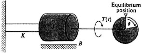
Figure 3.7 Torque applied to a moment of inertia, a twisting shaft, and a damping device.
The units of moment of inertia in the International System is kg m2, and in the English system it is slug ft2 or lb ft sec2. The units of the spring constant are newton meters/radian in the International System, and lb ft/radian in the English system.
This second-order differential equation can be written as two first-order differential equations by defining
The resulting state equations are given by
In vector form, these equations become
where