
3.2. STATE EQUATIONS OF ELECTRICAL NETWORKS
Before introducing the techniques for formulating the state equations and transfer-function representation of some common linear control-system devices, the subject of electrical networks is considered [1]. Specifically, it is the purpose of this section to illustrate how the engineer can represent the state equations of electrical networks [2]. The very same method is applicable to the analysis of control-system devices. Network equations of electrical circuits can be formulated from the basic laws of Kirchhoff. It is assumed that the reader is familiar with the corresponding loop and nodal techniques for analyzing electrical networks [1].
The loop equation of the basic RLC circuit illustrated in Figure 3.1 is given by
The current in the inductor and the voltage across the capacitor are usually considered to be the state variables of a network. Then the resulting state equations for this circuit can be formulated by relating the voltage across the inductor L and the current in the capacitor C as follows:
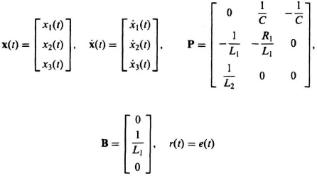
Defining the state variables as
the following state equations of the circuit are obtained:
These equations can be written
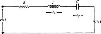
Figure 3.1 An RLC circuit.

As a second example, consider the electrical network of Figure 3.2. The state equations are obtained by writing the equation for the currents in the capacitors and the voltage across the inductors as follows:
If the state variables are defined as
the following state equations for this electrical network are obtained:
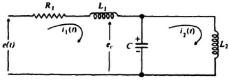
Figure 3.2 An electrical network.
These equations can be written as
where
These simple examples illustrate the general method for analyzing electrical networks utilizing the state-variable technique. The reader is referred to Reference [2] for a more detailed discussion of this particular subject. The same general method is illustrated next for the analysis of commonly used linear mechanical control-system devices.