
7.5. EXAMPLE FOR THE DESIGN OF A SECOND-ORDER CONTROL SYSTEM
In this section we consider the design and resulting performance of the second-order system by means of cascade and minor-loop rate-feedback techniques. This problem is useful in unifying concepts which were introduced in Chapters 4, 5, and 6, together with the design techniques illustrated in this chapter.
Let us consider the second-order system illustrated in Figure 7.18a. We will assume that the original forward-loop transfer function G0(s) is given by
The closed-loop transfer function, C(s)/R(s), is given by
or
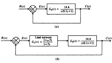
Figure 7.18 Design of a second-order system.
Comparing Eqs. (4.3) and (7.44), we observe that the undamped natural frequency ωn and damping ratio ζ of the system are given by
and
ζ = 0.417.
If the system is subjected to a unit step input, the transient response will have the form shown in Figure 4.4 (interpolate between ζ = 0.4 and ζ = 0.6). The maximum percent overshoot can be obtained from Eq. (4.33) and is found to be 23.5%.
Let us assume, for this application, that it is desired to have a critically damped system (ζ = 1). We will demonstrate how this can be achieved using a cascaded network and minor-loop rate feedback.
Figure 7.18b illustrates the form that the system illustrated in Figure 7.18a would have if a cascaded network were used. We attempt to achieve a damping ratio equal to 1 using a phase-lead network, where
As was assumed previously, in Section 7.2, we assume that T ≪ αT, and therefore Gc(s) can be approximated by (proportional plus derivative control)
![]()
The closed-loop system transfer function for this case was derived in Section 7.2 [see Eq. (7.13)] as

The equivalent damping ratio for this situation was derived in Section 7.2 [see Eq.(7.15)] as
The object in this problem is to design ζeq = 1 for the case where
![]()
Substituting the values into Eq. (7.50), we find that
αT = 0.0972.
We know that the resulting system will be stable and critically damped, and will have a steady-state response error for a unit step input of zero. The steady-state response error of the system to a unit ramp input was derived [see Eqs. (7.18) and (7.20)] as
Let us next attempt to achieve the same type of performance using minor-loop rate feedback. Figure 7.19 illustrates the form that the system illustrated in Figure 7.18a would have if minor-loop feedback were used. Our goal is to achieve a damping ratio of ζ = 1. The closed-loop system transfer function for this case was derived previously, in Section 7.2 [see Eq. (7.26)] as
The equivalent damping ratio for this configuration was derived in Section 7.2 [see Eq. (7.28)] as
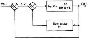
Figure 7.19 Minor-loop feedback added to the system shown in Figure 7.18a.
The object in this problem is to design ζeq = 1 for the case where
and
Substituting these values into Eq. (7.53), we find that
Notice that b and αT are identical.
We know that the resulting system will be stable and critically damped, and will have a steady-state response error of zero for a unit step input. The steady-state response error of the system to a unit ramp input was derived [see Eq. (7.31)] as
The increase has been accounted for in Section 7.3; by using a high-pass filter in the feedback path to block a steady-state output from the rate feedback, the steady-state error can be reduced to 0.0695.