
1.5. MODERN CONTROL-SYSTEM APPLICATIONS WITH A PREVIEW OF THE FUTURE
Feedback control systems are to be found in almost every aspect of our daily environment. In the home, the refrigerator utilizes a temperature-control system. The desired temperature is set and a thermostat measures the actual temperature and the error. A compressor motor is utilized for power amplification. Other applications of control in the home are the hot-water heater (see Problem 1.3), the central heating system, and the oven, which all work on a similar principle. We also encounter feedback control systems when driving our automobile. Automatic control systems are used for maintaining constant speed (cruise control), constant temperature (climate control) steering, suspension, engine control, and to control skidding (antiskid system) [3–5].
In industry the term automation is very common. Modern industrial plants utilize robots for obtaining temperature controls, pressure controls, speed controls, position controls, etc. The chemical process control field is an area where automation has played an important role [6]. Here, the control engineer is interested in controlling temperature, pressure, humidity, thickness, volume, quality, and many other variables. Areas of additional interest include automatic warehousing [7] and inventory control [8] and automation of farming [9].
In this section, I present the state of the control-system field by illustrating its application in the following important aspects of engineering: robotics, space travel, commercial rail and air transportation, military systems, surface effect ships, hydrofoils, biomedical control systems and photographic automatic focus control systems. In addition, the use of control theory to model systems unrelated to control is illustrated. Illustrations will be given of current applications and future plans of control-system design. Because a feature of this book is the application of the theory presented to practical design examples, these illustrations will also serve as models for the problems used throughout the book.
A. Robotics
Robotics has been a very important field for the application of control systems. In the 1960s robots began to be recognized as important devices to aid manufacturing; their application to a wide variety of manufacturing systems has mushroomed since then. Control theory is needed for obtaining the desired motion or force needed; the field of robotics also depends on the use of sensors for vision, and computers for programming these devices to accomplish their desired tasks.
Robots have been created to perform a wide variety of tasks spanning the fields of manufacturing, space vehicle missions, and hospital care. A major application of robotics has been in automating the manufacturing process. Figure 1.12 illustrates a line of automobiles and robots at the Ford Motor Company’s Chicago assembly plant. This is the same plant which produced the legendary Model T. Following the plant’s modernization program, it now produces the Ford Taurus and Mercury Sable car lines. Some of the new high-technology additions at the plant include robotic sealing of side windows and vehicle underbodies, automatic feeding of car parts to the assembly process, and new overhead conveyors.
Robots have also been incorporated into NASA’s space shuttle. Figure 1.13 is an artist’s concept of the Canadian-built remote manipulator system (RMS), which is a robot arm-like device. The robot arm is shown lifting the West German MBB shuttle pallet satellite (SPAS-01) from the cargo bay of the Earth-orbiting space shuttle Challenger.
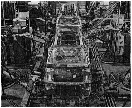
Figure 1.12 A line of automobiles and robots at Ford Motor Company’s Chicago Assembly Plant which produced the legendary Model T. (Courtesy of the Ford Motor Company)
Robots have also been applied to helping people. Figure 1.14 illustrates Help-Mate™, made by Transitions Research Corporation (TRC), which is a mobile robotic materials transport system designed to perform mundane fetch-and-carry tasks that would ordinarily be performed by nurses and aides in hospitals and long-term-care facilities [10]. HelpMate™ is a self-guided robot which relieves highly trained personnel to carry out more important duties. This robot uses vision, ultrasonic and infrared proximity sensors, and dead reckoning to navigate through hallways, ride elevators, and avoid obstacles encountered along its route. It can transport special-request meal trays, laboratory samples and specimens, pharmacy medications, patient medical records, administrative reports, etc. [11].
Analysis and design of robots similar to these illustrations are contained in several examples in this book.
B. NASA Space Programs and Associated Trainers
At the forefront of the space program is the International Space Station. Figure 1.15 shows an artist’s concept of the baseline configuration of the International Space Station. It is an international space complex comprised of the permanently manned orbiting and unmanned scientific platforms to be placed into orbit. Overall configuration is about 500 ft across, 200 ft tall, and 145 ft deep. The illustration shows a space shuttle orbiter being used to bring up sections of the station for assembly in orbit by astronauts. An eight-person crew will live and work aboard the manned base’s three laboratory modules—one each from the United States, Japan, and the European Space Agency—and the United States-provided habitation module, which was designed for use for up to six months at a time. Canada is providing the Mobile Servicing System, which features a robot arm three times stronger than the shuttle’s remote manipulator discussed previously under robotics. Ultimately, the International Space Station will serve as a gateway to the stars, providing an in-orbit assembly, test, and departure point for piloted missions back to the Moon, to Mars, and beyond. This book analyzes several applications of space vehicles. Figure 1.16 illustrates the block diagram of the attitude control system of a typical space vehicle. Chapter 11 is dedicated to optimal control theory, which is applied to the space-attitude-control problems concerned with minimizing response time, fuel consumption, and energy consumption of space vehicles. The lunar soft-landing probe, is synthesized from the viewpoint of optimal control theory in Chapter 11, as well.

Figure 1.13 Artist’s concept of the Canadian-built remote manipulator system (RMS), a robotarm-like device. The robot arm is shown lifting the West Germany MBB shuttle pallet satellite from the cargo bay of the Earth-orbiting space shuttle Challenger. (Official NASA photo)
An important aspect needed to support the success of the NASA Shuttle and the International Space Station is training the astronauts to successfully perform their missions. Figure 1.17 is a photograph of the NASA Shuttle Mission Simulator Motion-based trainer which simulates the shuttle cockpit with full six-degree-of-freedom motion cues. This simulator enables astronauts to train for the operation of the mission. Additionally, it must train for assembling the space station using the shuttle robotic manipulator arm (see Figure 1. 13), controlling the embryonic space station through station-compatible communications, docking with the space station, and transferring equipment and personnel. This simulator provides the capability to train astronauts and for mission-control ground crews to control the space shuttle through launch, ascent, orbit, de-orbit, and landing as well as for in-orbit activities such as experiment activation/deactivation, and satellite deployment and maintenance.
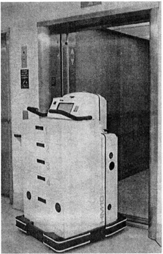
Figure 1.14 Robot HelpMate™, which is a mobile robotic materials transport system used to perform mundane fetch-and-carry tasks in hospitals and nursing homes. (Courtesy of TRC)
C. Rail Transportation
Great advances have been made in rail and air transportation, and more are planned. Magnetic-levitation (MAGLEV) train systems are in various stages of planning, design, test, and limited operation in Japan, Berlin, and the United States [12,13]. MAGLEV’s main advantages over conventional rail systems are its relative lack of noise and vibration, lower power consumption, and lower maintenance costs, because there is no need for components such as a rotating motor [13]. In Japan, a MAGLEV system is being constructed for a 40-km-long test track in Yamanashi prefecture, 70 percent of which will be a tunnel. The 500-kph, or 310-mph, electrodynamically suspended (repulsion mode) technology used by Japan’s MAGLEV, named the Linear Express, will be tested under operational conditions [14]. The test track could form part of a new Chuo line, supplying service between Tokyo and Osaka early in the next century. It is estimated that it would consume half the energy of an airplane in moving the same amount of people [15].

Figure 1.15 Artist’s concept of the International Space Station. (Official NASA photo)
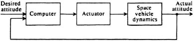
Figure 1.16 The attitude-control system of a typical space vehicle.
The Central Japan Railway Company’s Linear Express MAGLEV technology makes use of superconductivity magnets which function on the principle of magnetic repulsion [16]. The superconducting magnets are attached to the bottom of the train, and the U-shaped guideway has coils which have a current induced in them as the train gains speed. The coils then become magnetic and repel the magnets on the bottom of the train. The Linear Express uses these principles to levitate 10 cm above the ground. (Regular magnets could only elevate the train 1 cm, which would mean that high-precision tracks and control systems would be necessary.) It is equipped with rubber wheels which function until the vehicle reaches 100 kph, when the repulsion is sufficient to elevate the train (in a manner similar to the takeoff of an airplane.) The Linear Express obtains forward propulsion along the tracks using magnets having south and north poles arranged in an alternating manner. The attraction and repulsion of the magnets, which are changed continuously by computers so that repulsion forces act from behind and attraction forces act from the front, propel the train forward. Figure 1.18 is a photograph of the Linear Express (serial 002) which was used on a test track on the island of Kyushu.
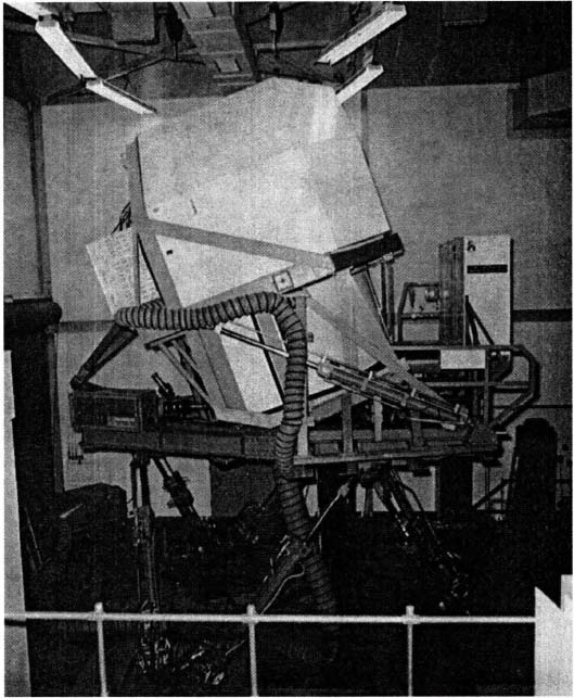
Figure 1.17 NASA Shuttle Mission Motion-based trainer simulates the shuttle cockpit with full six-degree-of-freedom motion cues. (Courtesy of: Hughes Training, Inc./Arlington, TX)
Figure 1.19 is a photograph of Japan’s new Series 100 “bullet” high-speed trains, or Shinkansen, which have greatly facilitated intercity travel in Japan [17–20]. The Shinkansen long-distance high-speed railways include the Tokaido and Sanyo Shinkansen, which runs southwest from Tokyo, and the Tohoku and Joetsu Shinkansen, which serves the regions to the northeast. The maximum speed for the Tohoku and Joetsu Shinkansen is now 240 kph (148.8 mph). (It is interesting to note that the MAGLEV Linear Express can attain speeds twice as fast as the Shinkansen bullet trains. Energy consumption of the Shinkansen is only 21 percent that of an airplane, and 19 percent that of an automobile [19,20].
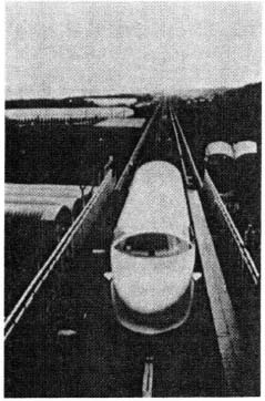
Figure 1.18 Photograph of the magnetic levitation train, the Linear Express, test vehicle (serial 002) which was used on a test track on the island of Kyushu, Japan. (Courtesy of Japan Railways Group)
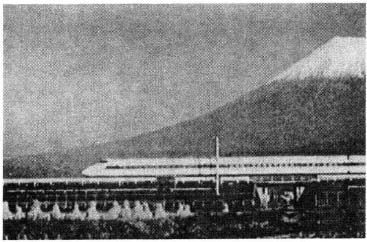
Figure 1.19 New Series 100 “bullet” high-speed trains, or Shinkansen, have greatly facilitated intercity travel in Japan. (Courtesy of Japan Railways Group)
The Shinkansen uses automatic verification of signals and brake control. In addition, an automated traffic control system regulates the trains and their routing, permitting safe, high-speed operation.
Figure 1.20 illustrates the general position-control concepts of such a high-speed automated train system [17]. Observe from the block diagram that it contains a position-measuring loop and a velocity-measuring loop. Position can be measured from the rotation of the train’s wheels. Speed can be measured by using velocity-sensing devices such as tachometers. The control computer system monitors the positions and speeds of all trains in the system and issues control signals via a high-speed communication system.
D. Air Transportation
In November 1990, McDonnell Douglas delivered the first of its MD-11 jets to the Finnish airline, Finnair Oy [21]. Figure 1.21 is a photograph of the MD-11, and Figure 1.22 is a photograph of its advanced flight deck [22,23]. The MD-11 has a two-seat cockpit with automatic system controllers in the overhead panel that monitor and configure fuel, hydraulic, electrical, and environmental systems. Each system is controlled by two redundant computers. The advanced flight deck features six cathode-ray-tube displays, digital instrumentation, wind-shear detectors and guidance devices, a dual flight management system that helps conserve fuel, and a dual digital automatic flight control system (autopilot) with fail-operational capability. Computerized system controllers perform automated normal, abnormal, and emergency checklist duties for the MD-11’s major systems. The flight control computer, formerly called the automatic pilot and flight director, includes an automatic throttle and a longitudinal stability augmentation system, which enhances the pitch stability of the aircraft.
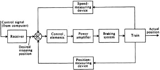
Figure 1.20 Automatic position-control system of a high-speed automated train system.
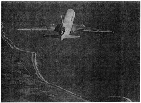
Figure 1.21 Photograph of the McDonnell Douglas MD-11. (Courtesy of the McDonnell Douglas Corporation)
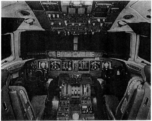
Figure 1.22 Photograph of the advanced flight deck of the McDonnell Douglas MD-11. (Courtesy of the McDonnell Douglas Corporation)
Several problems are included in this book that analyze and design the attitude-control systems of aircraft. Figure 1.23 illustrates the block diagram of a typical autopilot system for an aircraft.
E. Tilt Rotor Aircraft
Tilt rotor aircraft which can take off and land vertically, and also fly as a fixed-wing aircraft, have found great use in military applications. They provide the speed and range of a turboprop airplane and the vertical takeoff and landing capability of a helicopter. Figure 1.24 is a photograph of the Bell Boeing V-22 Osprey military tilt rotor which is a twin-turbine, vertical-lift, transport that is used by the U.S. Marine Corps, Navy, Air Force, and Army [24]. Bell Helicopter Textron and the Boeing Company have initiated a program to develop and manufacture the Bell Boeing 609 illustrated in Figure 1.25. It will be a six-to-nine passenger civil tilt rotor aircraft, which builds on technology developed for the V-22 Osprey military tilt rotor, [25, 26]. Anticipated uses for the Bell Boeing 609 are for executive transportation, search-and-rescue, offshore oil operations, emergency medical evacuation, disaster relief, and government support for drug enforcement, and border patrol. It is anticipated that the Bell Boeing 609 will be the first of a range of tilt rotor aircraft for civil and commercial markets which will eventually include large tilt rotors that could be used by airlines to fly passengers between city centers.

Figure 1.23 A typical autopilot system for an aircraft.
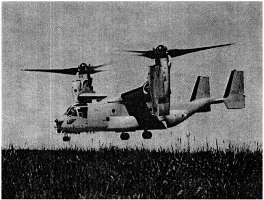
Figure 1.24 Photograph of the Bell Boeing V-22 Osprey military tilt rotor which is a twin-turbine, vertical-lift, transport used by the U.S. Marine Corps, Navy, Air Force, and Army. (Photo by Boeing)
F. Helicopters and Associated Trainers
Helicopters are a very important transportation link for the military and for civilian use. As an example, Figure 1.26 is a photograph of the UH-60 Black Hawk combat assault helicopter airlifting M-102 mm howitzers during Operation Desert Shield. How do you train a pilot to fly a complex helicopter like the UH-60 Black Hawk helicopter? Figure 1.27 is a photograph of the UH-60 Black Hawk Flight Simulator which provides Black Hawk pilots and co-pilots with basic, transition, refresher, and advanced training in flight operations, emergency procedures, and combat tactics and advanced combat skills. Figure 1.27 illustrates the trainer station, which moves on a dynamic six-degree-of-freedom motion system, and provides a realistic cockpit environment for the pilot and the co-pilot. The simulated cockpit is an authentic replica of the interior of the production helicopter. All items look, feel, move, and operate as they do in a UH-60 Black Hawk helicopter.
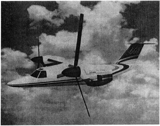
Figure 1.25 Photograph of the planned Bell Boeing 609 civil tilt rotor which can be used in such applications as offshore oil exploration. It is estimated that it could reduce the time it takes to ferry personnel and equipment to an oil rig to half the current time it takes helicopters. (Photo by Bell Boeing)
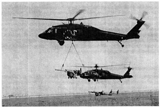
Figure 1.26 A UH-60 Black Hawk Helicopter airlifting M-102mm howitzers during Operation Desert Shield. (Official U.S. Navy Photo (released))
Basic training tasks which can be accomplished in the UH-60 trainer include ground operations, takeoff, hovering, basic/advanced flight, formation flight maneuvers, emergency procedures, and navigation. All UH-60 simulators have an instructor operator station which enables the instructor to initialize the training mission, select and edit initial conditions, position and reset the trainer, insert malfunctions, and program demonstration maneuvers [27].
G. Military Systems
Great advances have been made in the design of military aircraft, ships, and submarines. Figure 1.28a is a photograph of the U.S. Air Force’s F-15 eagle, an all-weather, extremely maneuverable tactical fighter designed to gain and maintain air superiority in aerial combat [28]. It contains electronic systems and weaponry to detect, acquire, track, and attack enemy aircraft. The avionic system includes an inertial navigation system, a tactical navigation system, an instrument landing system, and a central digital computer. The inertial navigation system permits the Eagle to navigate anywhere in the world.
Figure 1.28b is a photograph of the new F-22 which is regarded as the world’s most advanced fighter [29]. Plans are to have the F-22 fighter replace the F-15C Eagle fighter after the turn of the century. The primary objective of the F-22 is to establish absolute control of the skies through the conduct of counter-air operations. This fighter also has an inherent precision ground attack capability. In order to make the F-22 twice as effective as the F-15, extensive use has been made of computers. The exponential explosion of computer technology in the last 10 years has allowed the F-22 to exploit this capability. For example, the computer used in the Lunar Module (which is analyzed in this book in Chapter 2, Problem 2.46 and illustrated in Figure P2.46, and in Section 11.7) operated at 100,000 operations per second and had 37 kilobytes of memory. Today, the F-22’s main mission computers, which are called Common Integrated Procesors or CIPs, operate at 10.5 billion instructions per second and have 300 megabytes of memory. These numbers represent 100 000 times the computing speed and 8000 times the memory of the Apollo moon lander.

Figure 1.27 U.S. Army’s Black Hawk (UH-60) Flight Simulator simulates the helicopter and accomplishes all of the functions related to helicopter operations. The trainer station pictured moves on a six-degree-of-freedom motion system and provides a realistic cockpit environment for the pilot and co-pilot. (Courtesy of Hughes Training, Inc., Arlington, TX)
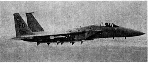
Figure 1.28(a) Photograph of the U.S. Air Force’s F-15 Eagle Aircraft. (Official U.S. Air Force photo)
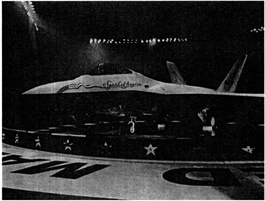
Figure 1.28(b) The F-22 Raptor is unveiled at the Lockheed Martin Aeronautical Systems in Marietta, Georgia. (F-22 Team Photo courtesy of Lockheed Martin Aeronautical Systems)
Another illustration of the application of advanced automatic control theory to the military is in the area of strategic missile submarines. Figure 1.29 is a bow view of the nuclear-powered strategic submarine USS Tennessee (SSBN-734) underway. The Trident fitted Strategic Missile Submarine (SSBN) force provides the principle USA strategic deterrent. These huge submarines are 560 ft × 42 ft × 36.4 ft in size and they contain 24 Lockheed Trident II (D5) stellar inertial guidance missiles. Trident missile accuracy is as good as ground-base systems [45]. Control systems are used in almost every aspect for controlling this modern submarine. For example, suppose the submarine is required to maintain a fixed depth automatically. This operation is called “hovering.” It is accomplished by an automatic control system which compares the desired depth (derived as a voltage) with the voltage output of a depth detector which operates on the principle that the water pressure increases with depth. This difference is used to control the angular position of the submarine’s planes which then controls the submarine’s depth through the submarine’s dynamics. The block diagram for this control system is illustrated in Figure 11.3ii, which is presented as part of Illustrative Problem 11.3, and in Figure P2.57 which is presented as part of Problem 2.57.

Figure 1.29 Photograph of the nuclear-powered strategic missile submarine USS Tennessee (SSBN-734). (Official U.S. Navy Photograph)
Several examples of analyzing and designing control systems associated with these kinds of military weapon systems are contained in this book (e.g., automatic depth-control systems for submarines).
H. Surface-Effect Ships and Hydrofoils
Modern control has made a major contribution in the control of two new classes of ships: surface-effect ships and hydrofoils. Figure 1.30a is a photograph of U.S. Coast Guard surface-effect ships (WSES). These new patrol craft are used by the U.S. Coast Guard, primarily for enforcement of laws and treaties. Using the surface-effect principle, it can attain a maximum speed which is greater than 30 knots [30]. Lift engines drive fans that create a pressurized air cushion under the vessel; this lifts the vessel and, therefore, reduces drag and draft. The two solid side walls pierce the water surface and form a catamaran hull; the air cushion is sealed by flexible rubberized skirts at the bow and stern.
Hydrofoils are another important illustration of the advancement in the design of ships. Figure 1.30b is a photograph of the U.S. Navy hydrofoil USS Pegasus (PHM-1) which is a modern, missile-equipped patrol boat [31]. The PHM class of vessels can be adapted to such diverse roles as antisubmarine warfare, fisheries law enforcement, and the protection of offshore resources. The bow foil provides approximately 31.8 percent of the dynamic lift, and the aft foil provides approximately 68.2 percent. The bow foil uses a strut that rotates in order to provide directional control and reliable turning rates in heavy seas. Control and lift are also provided at takeoff and in flight by flaps connected to the trailing edges. An automatic control system, the helm, and the throttle provide continuous dynamic control during take off, foil-borne operation, and landing. Control of the PHM is achieved by sensing its attitude, boat-motion rates, and acceleration. These quantities are then compared to the desired values in a closed-loop feedback system such as those described in Section 1.3. Errors between the desired and actual quantities are then used by hydraulic actuators to reposition the control surfaces (trailing edge flaps on each of the foils and the rotating bow foil strut) in order to achieve the desired quantities.
The control systems used on these kinds of ships are analyzed and designed in several examples in this book.
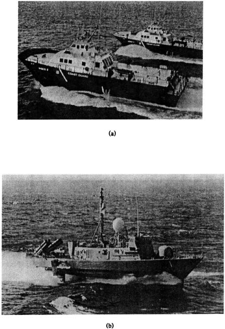
Figure 1.30 (a) Photograph of the U.S. Coast Guard Surface-Effect Ships (WSES) (Courtesy of the U.S. Department of Transportation), (b) Photograph of the U.S. Navy Hydrofoil, USS Pegasus (PHM-1). (Official U.S. Navy photo)
I. Biomedical Control Systems
There are many applications of control-system concepts in the biomedical field, including prostheses [32–38], and controlling the human heart using a pacemaker. In this section we illustrate the former; the latter is illustrated in an application problem in Chapter 5 (Problem 5.14).
As an illustration of the application of control system concepts to aid above-elbow amputees, let us consider the working of the Boston Elbow [36–40] which is illustrated in Figure 1.31. Use is made of minute electrical signals on the skin in the stump, which are generated by tension in the underlying muscles. These minute signals, which range from 5 to 1000 μV, are denoted as myoelectric, and great care must be given to providing very good instrumentation for their amplification because these minute signals must operate in the presence of much larger external noise caused by interference due to such devices as fluorescent lamps and radio transmitters. The amplified signal is used to drive a battery-powered miniature high-speed electric motor containing a gear reducer to reduce its speed to that compatible with human hand functioning.
The Boston Elbow can be operated in various control-system configurations. For example, it can be controlled in an on-off mode using a logical on-off muscular signal, and it can be operated in a mode in which the signals are proportional to muscle tension. Variation in muscle tension, which results in a proportional myoelectric signal, is used as part of a proportional control system. Because an amputee uses the muscles in much the same way as before the amputation, a small amount of tension will cause the Boston Elbow to move slowly, and increased muscle activity will make it move faster. Because the prosthesis has no feeling, both elbow position and grasp must be controlled by visual feedback. Therefore, the feedback loop is closed by the humans visual feedback in a manner similar to that discussed in Section 1.4 for driving an automobile.
The Boston Elbow has also been operated in a closed-loop positioning control system mode on an experimental basis [37,38]. In the application of such a configuration to a prosthetic hand, the actual output signal is the finger position. For generation of the feedback signal, the finger drives a second transducer. Differences in signals between the finger’s feedback transducer and the input transducer are amplified to drive the motor. For example, if the transducer is moved one-third of the way, the hand will settle at a position one-third open. This closed-loop configuration has the advantage that the user can feel the position of the body part operating the control-system transducer. Therefore, the user’s hand will open to a given position without having to use visual feedback.

Figure 1.31 The Boston Elbow uses myoelectric signals on the skin in the stump, which are generated by tension in the underlying muscles, for controlling purposes. (Courtesy of the Liberty Mutual Insurance Group, Boston)
J. Photographic Automatic Focus Control Systems [41, 42]
It is not necessary to have to consider robotics, aircraft, space, and military systems to illustrate examples of automatic control systems. Automatic control systems are also used in a very wide array of everyday applications such as your camera. Figure 1.32a is a cutaway view of the Nikon N6006 35-mm camera which uses a charge-coupled device (CCD) that converts images into electrical signals as part of its automatic focusing system. At the core of the N6006’s automatic focus is Nikon’s Advanced AM200 Autofocus Sensor Module, which is an autofocus detection system, containing a high-density 200 CCD sensor which can detect detail even in dim light conditions. Automatic focusing systems are implemented by focusing the center of the image on a CCD array through two lenses. Focusing, which is related to the separation of the two images on the CCD, is sensed by the camera and a microcomputer drives the lens and focuses the image. Automatic focusing systems compare the actual position of the lens with the desired position of the lens which is obtained by pointing the camera at the object. Figure 1.32b shows a block diagram representation of automatic focusing control systems which compare the desired and actual lens positions. The control system contains a microcomputer, a CCD, an amplifier, and a motor.
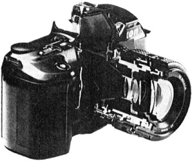
Figure 1.32(a) Cutaway view of the Nikon N6006 35-mm camera which shows portions of its automatic focusing system. (Courtesy of Nikon Inc.)

Figure 1.32(b) Functional block diagram representation of an automatic focusing system.
K. Modeling Systems Unrelated to Control
Automatic control theory has also been applied for modeling the feedback processes of many systems unrelated to control. An example of this is the modeling of our economic system in order to understand it better. Our economic system contains many feedback systems and regulatory agencies. Figure 1.33 illustrates a crude model of the economics concerned with national income, government policy on spending, private business investment, business production, taxes, and consumer spending. This type of feedback model assists the analyst in understanding the overall effects of government policy and private business investment on the national income. Several other examples of using control theory to model systems unrelated to control are contained in the book (e.g., model of a fish pond in Problem, 2.59).
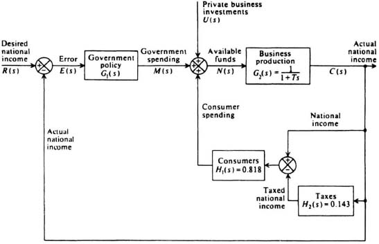
Figure 1.33 Economic feedback relationship model concerning national income, government policy on spending, private business investment, business production, taxes, and consumer spending.