
3.6. TRANSFER-FUNCTION REPRESENTATION OF THERMAL SYSTEMS
If the assumption is made that the temperature of a body is uniform, then a number of thermal systems can be represented by linear ordinary differential equations [13]. This approximation is reasonably correct for relatively small configurations. This section specifically considers a hot-water heating system as an example of a typical thermal system.
Figure 3.27 illustrates an electric hot-water heating system. The object of this system may be, typically, to supply hot water in a home. Any demand for hot water in the home causes hot water to leave and cold water to enter the tank. In order to reduce heat loss to the surrounding air, the tank is insulated. A thermostatic switch turns an electrical heating element on or off in order to maintain a desired reference temperature.
The law of conservation of energy requires that the heat added to the system equals the heat stored plus the heat lost. This can be expressed by the relationship
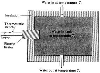
Figure 3.27 Electric hot-water heating system.
Qh(t) = heat flow supplied by heating element,
Qc(t) = heat flow into storage in the water in the tank,
Qo(t) = heat flow lost by hot water leaving tank,
Qi(t) = heat flow carried in by cold water entering tank,
Ql(t) = heat flow through insulation.
It can be shown that
where
C = thermal capacity of water in tank
Tt(t) = temperature of water in tank;
where
V(t) = water flow from tank
H = specific heat of water
where
Ti(t) = temperature of water entering tank; and
where
Te(t) = temperature of air surrounding tank
R = thermal resistance of insulation, stagnant air film, and stagnant liquid film.
Substitution of Eqs. (3.145)–(3.148) into Eq. (3.144) yields the expression
The thermal model presented, so far has considered Tt(t), Ti(t), Te(t), and V(t) as variables. For the specific condition where V is a constant and Te(t) = Ti(t), Eq. (3.149) reduces to the expression
where Tr(t) = temprature of the water in the tank above the reference Te(t). The Laplace transform of Eq. (3.150) is given by
The transfer function of this system, defined as the ratio of the output Tr(s) so the input Qh(s) is given by
and its simple block diagram is illustrated in Figure 3.28.