
2.18. OPERATIONAL AMPLIFIERS [9]
Operational amplifiers, usually referred to as “op amps,” are very commonly used in control systems for performing differencing of signals, integration, amplifying signals in sensor circuits, and in filters used for compensation. The fundamental component of an operational amplifier is a high gain dc voltage amplifier. By appropriately choosing the input and feedback impedances, any desired analog computer characteristic can be obtained easily. These devices are of relatively high gain in the range of 105 to 107. Due to these high gains, the drift problems associated with dc amplifiers are greatly magnified. To minimize the drift, highly regulated power supplies, temperature-compensated precision resistors, and feedback techniques are designed into each dc amplifier.

Figure 2.19. A feedback control system containing lour feedback paths, an input, R(s), and a disturbance input, U(s). (a) The block diagram. (b) The signal-flow graph.
Let us consider the basic operational amplifier circuit illustrated in Figure 2.20. It consists of an input circuit impedance, Zi, a feedback impedance, Zf, and the input impedance of the dc amplifier, Zg. The open-loop gain of the amplifier is assumed to be K. The gain of the feedback circuit, eo/ei, can be obtained from the following set of equations:
Solving Eq. (2.136) and (2.137) for ii and if, respectively, and then substituting these values into Eq. (2.138), the following equation is obtained:
Substituting eg into Eq. (2.139), the overall gain of the feedback operational amplifier is obtained.

In practice, Zg is usually very much larger than Zi and Zf. In addition, as mentioned previously, K is a very large number, greater than 105. Therefore, Eq. (2.141) can be approximated by the following relationship:
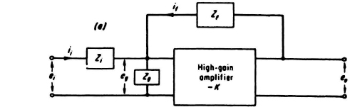
Figure 2.20 Basic operational amplifier circuit.
The corresponding simplified representation of the operational amplifier is illustrated in Figure 2.21.
Observe from Eq. (2.142) that the ratio of Zf to Zi determines the characteristics of the operational amplifier. For example, if Zi and Zf are resistances of equal value, we obtain a sign changer. However, if Zf is greater than Zi, we obtain an amplifier. In addition, if the feedback is a capacitor and the input element is a resistor, the operational amplifier behaves as an integrator where
By reversing the capacitor and resistor, a differentiator results where
The circuit of Figure 2.20 can be easily modified to produce an analog adder, as indicated in Figure 2.22. This circuit can be analyzed easily if it is recognized that eg is essentially zero for operational amplifiers. This can be proved for the circuit of Figure 2.20 from Eqs. (2.136) through (2.139). Solving for the ratio of eg to ei. and simplifying, the following equation is obtained:
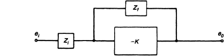
Figure 2.21 Simplified representation of the operational amplifier.
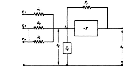
Figure 2.22 An adder operational amplifier.
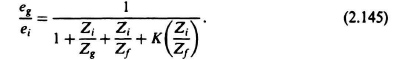
Since K is greater than 105, this equation clearly illustrates that eg is maintained practically at zero volts. This is also true for the operational amplifier circuit of Figure 2.22. Therefore, by summing all of the currents flowing into node X of Figure 2.22 the following equation is obtained.
Since we proved that eg is zero, this equation reduces to the following form:
Equation (2.147) can be put in the following simpler format:
where
An = Rf/Rn.
Equation (2.148) clearly illustrates the additive characteristic of this circuit. The gains associated with each input are conventionally marked on the block diagram of the operational amplifier.
In the case of operational amplifiers, one or more components of the device are purposely left out in order to make it more flexible. These components can then be externally selected in order to vary the closed-loop gain and bandwidth, and have the operational amplifier perform as an integrator, multiplier, sign changer, or adder.
Table 2.6 summarizes the operation, circuit, and symbology of several common operational amplifier computing devices. The circuits illustrated depend on the high gain of a dc amplifier, K. The higher the gain of this amplifier, the more exact is the operation performed.