
6.19. CONTROL SYSTEMS CONTAINING MULTIPLE GAIN MARGINS
It was shown in Figure 6.16 during the discussion of the Nyquist diagram that some control systems can have more than one phase margin. Figure 6.15 illustrated the Nyquist diagram of a control system which contained two gain margins. This section will address how multiple gain margins appear on both the Bode diagram and the root locus for the same control system.
Let us consider a unity-feedback control system whose forward transfer function, G(s), is given by the following:
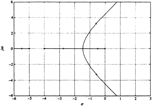
Figure 6.71 Computer-program-generated root locus plot for system defined by Eq. (6.143), and whose root locus was previously obtained using the rules of construction and shown in Figure 6.57.
The Bode diagram for this control system is plotted in Figure 6.72 with K set equal to one. It illustrates that this control system has a gain crossover frequency of 1.0 rad/sec, and a phase margin of −40°. There are two phase crossover frequencies, one at 3.4 rad/sec with a gain margin of 22 dB and one at 210.0 rad/sec with a gain margin of 64 dB. Since the phase margin is negative, this control system is unstable.
Let us now view this control system on the root locus illustrated in Figure 6.73, and we let K vary from zero to infinity. We see that the system is stable between the gains of 22 dB (12.59) and 64 dB (1590). This is a very interesting result as we now go back to the Bode diagram in Figure 6.72 and try to correlate this result. If we increase the gain by 22 dB, or from 1 to 12.59, then the new gain crossover frequency will be at 3.4 rad/sec and its phase margin will be zero. Increasing the gain more than 22 dB or more than 12.59, results in a positive phase margin and the control system is stable. If the gain is increased by 64 dB, or to 1590, then the phase margin will revert back to zero degrees phase margin. Increasing the gain to more than 1590 will cause negative phase margins, and the control system will be unstable.
Therefore, both the Bode diagram and the root locus agree that this control system is unstable for gains less than 12.59 (or 22 dB), it is stable for gains between 12.59 and 1590 (or between 22 dB and 64 dB), and it is unstable for gains greater than 1590 (or 64 dB). The analysis in this section using both the Bode diagram and the root locus for the same control system is used to introduce the next section where the Nyquist diagram, the Bode diagram, the Nichols chart, and the root locus are all used to analyze 12 commonly used transfer functions. The synergism among these methods complements each other method’s results and message.

Figure 6.72 Bode diagram for a unity-feedback control system whose forward transfer function is given by Eq. (6.190).

Figure 6.73 Root-locus diagram for a unity-feedback control system whose forward transfer function is given by Eq. (6.190).