2.12. TRANSFER FUNCTIONS OF COMMON NETWORKS
The control engineer depends heavily on passive networks to modify the transfer function of the feedback control system in order to promote stability, improve closed-loop performance, and minimize the effects of noise and other undesirable signals.
Figure 2.8a represents an electrical network which is used for integration or to provide a phase lag. This circuit obtains its integrating property from the fact that the voltage across the capacitor is proportional to the integral of the current through it. To determine the behavior of this network we must determine the transfer function relating input and output signals. The integrodifferential equations describing the behavior of this network are given by
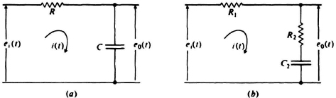
Figure 2.8 (a) An integrating or phase-lag network. (b) An integrating network with fixed high-frequency attenuation.
These differential equations can be solved for the relation between eo(t) and ei(t) by means of the Laplace transform; eo(0+) is assumed equal to zero. Thus one finds
Eliminating I(s) results in the transfer function
Notice from Eq. (2.110) that integration is possible only for those frequencies where |RCs| ≫ 1. It is important to note that this same transfer function can be obtained quite simply by determining the impedance of each circuit element and using the voltage divider rule. Thus
The impedance of the capacitance approaches a short circuit at very high frequencies, and ultimately it will have no output. This circuit is basically a low-pass filter whose high-frequency response is attenuated to a very large degree. Very often it is undesirable to have such a large attenuation at high frequencies. The circuit of Figure 2.8b limits this attenuation to a value of R2/(R1 + R2). The transfer function of the network is obtained directly by using the voltage divider rule. Thus,
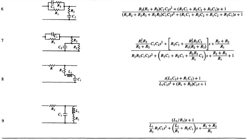
A tabulation of the foregoing results, together with other useful transfer functions which the control engineer will most likely encounter, is shown in Table 2.4. Network 1 is known as a differentiating or phase-lead network. Notice that it is basically a high-pass filter possessing very large attenuation at low frequencies. This attenuation can be limited to a finite value of R2/(R1 + R2) by network 3. A lag-lead network, which provides a phase lag at low frequencies and a phase lead at high frequencies, is shown as network 5. Networks 6 and 7 are slight modifications of network 5. Network 8 is used for eliminating unwanted frequency bands. Network 9 is used for passing signals in a narrow band of frequencies.