
3.8. ILLUSTRATIVE PROBLEMS AND SOLUTIONS
This section provides a set of illustrative problems and their solutions to supplement the material in Chapter 3.
I3.1. The torque–speed curve of a two-phase ac servomotor is illustrated where it is assumed that this characteristic can be represented by a straight line:

Figure I3.1
(a) Derive an equation for this torque–speed relationship, relating T and ω.
(b) The motor-shaft output power is the product of the motor’s derived torque, T, and its speed, ω:
P = Tω.
Derive the speed, ωmax, where the motor output power is a maximum.
(c) Derive an expression for the corresponding maximum motor-shaft output power, Pmax.
(d) Determine the maximum motor-shaft output power, Pmax, if the no-load motor speed, ωNL, is 5000 rev/min and the stall torque, T0, is 4 in-oz.
SOLUTION: (a) ![]()
(b) Substituting the equation for T derived in part (a) into the equation for the motor-torque output power
P = Tω
we obtain the following:
![]()
To find ωmax, we differentiate P with respect to ω as follows:
![]()
Therefore,
![]()
To check that this is a maximum, we take the second derivative of P as follows:
![]()
Since the second derivative is negative, ωmax is a maximum.
(c) Substituting the expression found for ωmax in part (b) into the expression for motor-shaft output power,
P = Tω
we obtain the following:
![]()
Substituting the expression for ωmax found in part (b) into the expression for T in part (a), we obtain the following:
Tmax = T0/2.
Substituting this expression for Tmax into the expression for Pmax′ we obtain the following:
![]()
(d) ![]()
Therefore,
Pmax = 2.726 watts
and Pmax occurs at a speed of 2500 rev/min.
I3.2. A control-system engineer needs to use an 8 : 1 gear reduction for a two-phase ac servomotor which is to be used for a positioning control system. The 8 : 1 gear reduction is to be made of two gear passes. The stock room has a limited number of gears available which can permit one of the following two configurations:
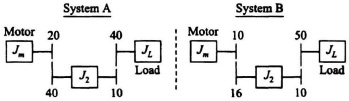
Figure I3.2
Each configuration has the same 8 : 1 gear reduction. The number of teeth on each gear is shown. At the instant of starting, the motor develops a torque TD. The control-system engineer wants to use the gear configuration which will provide the higher initial load accelertion.
(a) Write one parametric equation expressing the developed motor torque, TD, in terms of the inertias, the gear reductions, and the load acceleration, aL, with everything reflected to the motor shaft. (One parametric equation can represent both systems.)
(b) Assuming that JL = 16J2 = 4Jm, determine which system has the higher initial load acceleration.
SOLUTION: (a) Reflecting aL and all inertias to the motor shaft, we obtain the following:
![]()
where N1 represents the gear ratio between Jm and J2, and N2 represents the gear ratio between J2 and JL.
Simplifying this equation, we obtain the following:
![]()
(b) Setting the initial developed torques, TD, of system A and system B equal to one another, substituting JL = 16J2 = 4Jm, and using the gear ratios indicated, we obtain the following:
![]()
Factoring out JL and then canceling it from both sides of this equation, we obtain the following:
aLA(2 + 0.132 + 0.125) = aLB(2 + 0.1955 + 0.125).
Therefore,
aLA(2.257) = (2.3205)aLB
and
aLA = 1.00281aLB.
Therefore, we conclude that System A has the higher initial load acceleration.