
1.2. OPEN-LOOP CONTROL SYSTEMS
Open-loop control systems represent the simplest form of controlling devices. Their concept and functioning are illustrated by several simple examples in this section.
Figure 1.1 illustrates a simple tank-level control system. We wish to hold the tank level h within reasonable acceptable limites even though the outlet flow through valve V1 is varied. This can be achieved by irregular manual adjustment of the inlet flow rate by valve V2. This system is not a precision system, as it does not have the capability of accurately measuring the output flow rate through valve V1, the input flow rate through valve V2, or the tank level. Figure 1.2 shows the simple relationship that exists in this system between the input (the desired tank level) and the output (the actual tank level). This signal-flow representation of the physical system is called a block diagram. Arrows are used to show the input entering and the output leaving the control system. This control system does not have any feedback comparison, and the term open loop is used to describe this absence.
The angular position of a missile launcher being controlled from a remote source is illustrated in Figure 1.3. Commands from a potentiometer located at a remote location activate the positioning of the missile launcher. The control signal is amplified and drives a motor which is geared to the launcher. The block diagram corresponding to Figure 1.3 is illustrated in Figure 1.4. The input is the desired angular position of the missile launcher, the output is the actual angular position of the missile launcher, and the control system consists of the potentiometer, power amplifier, motor, gearing between the motor and missile launcher, and the missile launcher. For accurate positioning, the missile launcher should be precisely calibrated with reference to the angular position of the potentiometer, and the characteristics of the potentiometer, amplifier, and motor should remain constant. Except for the potentiometer, the components that comprise this open-loop control system are not precision devices. Their characteristics can easily change and result in false calibration and poor accuracies. In practice, simple open-loop control systems are never used for the accurate positioning of fire-control systems because of the inherent possibility of inaccuracies and the risks involved.

Figure 1.1 Tank-level control-system.
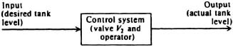
Figure 1.2 Tank-level control-system block diagram.
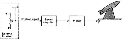
Figure 1.3 Controlling the position of a missile launcher from a remote location.
Figure 1.5 illustrates a field-controlled dc motor turning a cutting wheel at a constant speed. When a piece of wood is applied to the surface of the cutting wheel, it acts as a disturbing torque to the driving torque of the motor and results in a reduction of the speed of the cutting wheel, assuming that the control signal remains constant. This situation can be represented as shown in Figure 1.6. The symbol appearing between the motor and the load represents a subtractor.
The effect of disturbance torques, or other secondary inputs, is detrimental to the accurate functioning of an open-loop control system. It has no way of automatically correcting its output, because there is no feedback comparison. We must resort to changing the input manually in order to compensate for secondary inputs.
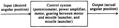
Figure 1.4 Missile launcher control-system block diagram.
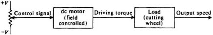
Figure 1.5 Field-controlled dc motor.
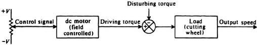
Figure 1.6 Field-controlled dc motor having a disturbance torque.