
5.7. ZERO-ERROR SYSTEMS
The transfer function of the general feedback system, containing a forward transfer function G(s) and a feedback transfer function H(s), is given by the general expression
From Eq. (5.26b) of Section 5.4, the error for this system can be expressed as*
It can be shown [2] that 1/(1 + Kp) is a function of Bm+1 − An+1, and it is necessary that Bm+1 = An+1 for zero steady-state error when the input is a step function. In addition, this implies that the forward transfer function contains at least one pure integrator as discussed previously in Section 5.4. From the general system transfer function of Eq. (5.50), it can be seen that there are many possible forms of C(s)/R(s) that will yield zero steady-state error with a step input. When the numerator consists of the constant Bm+1 the system is called a zero steady-state step error system [2]:
We can illustrate such a system with an example of a control system we have thoroughly analyzed in Chapter 4, the second-order control system, shown in Figure 4.1 which contains a single pure integrator. We also know from Table 5.1 that this control system has zero steady-state error to a unit step input (since G(s) has one pure integration). Solving for C(s)/R(s) from Figure 4.1, we obtain the following:
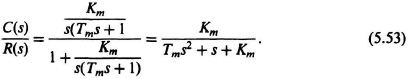
Equation (5.53) has the same form as Eq. (5.52) and, therefore, the control system shown in Figure 4.1 is a zero steady-state step error system.
It can be shown [2] that 1/Kv is a function of Bm+1 − An+1 and Bm − An. Therefore, for zero steady-state error with a ramp input, Bm = An and Bm+1 = An+1. In addition, this implies that the forward transfer function contains two or more pure integrators, as discussed previously in Section 5.4. A zero steady-state ramp error system occurs when the system transfer function is given by
To illustrate an example of a zero steady-state ramp error system, let us consider the control system shown in Figure 5.9. It contains two pure integrations and, therefore, n = 2 for Table 5.2, where we see that the steady-state error due to a ramp is zero. Let us determine the closed-loop transfer function of the control system shown in Figure 5.9 and verify that it has the same form as Eq. (5.54).
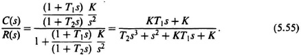
Therefore, the closed-loop transfer function of the control system shown in Figure 5.9 has the same form as the general equation (5.54), and it is, therefore, classified as a zero steady-state ramp error system.