
1.3. CLOSED-LOOP CONTROL SYSTEMS
Closed-loop control systems derive their valuable accurate reproduction of the input from feedback comparison. An error detector derives a signal proportional to the differences between the input and output. The closed-loop control system drives the output until it equals the input and the error is zero. Any differences between the actual and desired output will be automatically corrected in a closed-loop control system. Through proper design, the system can be made relatively independent of secondary inputs and changes in component characteristics. This section illustrates the closed-loop control system versions of the open-loop control systems considered in Section 1.2.
Figure 1.7 illustrates an automatic tank-level control version of the system shown in Figure 1.1. It can maintain the desired tank level h within quite accurate tolerances even though the output flow rate through valve V1 is varied. If the tank level is not correct, an error voltage is developed. This is amplified and applied to a motor drive which adjusts valve V2 in order to restore the desired tank level by adjusting the inlet flow rate. A block diagram analogous to this system is shown in Figure 1.8. Because feedback comparison is present, the term closed loop is used to describe the system’s operation.
Figure 1.9 illustrates an automatic missile launcher position control version of the system shown in Figure 1.3. This feedback system can be designed to position the launcher quite accurately on commands from potentiometer R1. Potentiometer R2 feeds a signal back to the difference amplifier, which functions as an error detector. Should an error exist, it is amplified and applied to a motor drive which adjusts the output-shaft position until it agrees with the input-shaft position, and the error is zero. The block diagram shown in Figure 1.8 is also applicable to this system. The input would be the desired angular position, the output would be the actual angular position, and the control system would consist of the potentiometer power, amplifier, motor gearing between the motor and missile launcher, and the missile launcher.
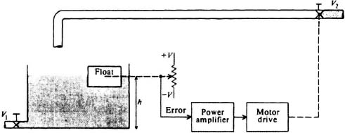
Figure 1.7 Automatic tank-level control system.
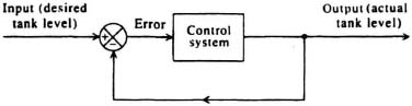
Figure 1.8 Block diagram of a closed-loop system.
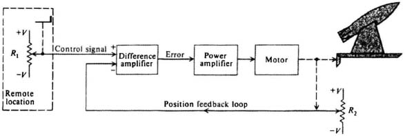
Figure 1.9 An automatic positioning system for a missile launcher.
An automatic speed-control version of a field-controlled dc motor, which was shown in Figure 1.6, is illustrated in Figure 1.10. This feedback system has the capability of maintaining the output speed relatively constant even though disturbing torques may occur. A tachometer, which functions as a transducer that transforms speed to voltage, is the feedback element for this control system. Should the output speed differ from the desired speed, the difference amplifier develops an error signal which adjusts the field current of the motor in order to restore the desired output speed.
Feedback control systems used to control position, velocity, and acceleration are very common in industrial and military applications. They have been given the special name of servomechanisms. With all their advantages, feedback systems have a very serious disadvantage, because the closed-loop system may inadvertently act as an oscillator. Through proper design, however all the advantages of feedback can be utilized without having an unstable system. A major task of this book is to determine how this may be accomplished for several kinds of systems.
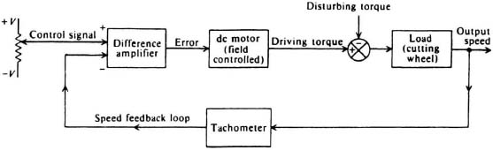
Figure 1.10 Automatic speed control for a field-controlled dc motor.