
PROBLEMS
3.1. (a) For the mechanical translational system illustrated in Figure P3.1, write the differential equation relating the position y(t) and the applied force f(t).
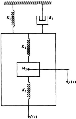
Figure P3.1
(b) Determine the transfer function Y(s)/F(s).
(c) Determine the phase-variable canonical vector form of this system.
3.2. (a) For the mechanical translational system illustrated in Figure P3.2, write the differential equation relating the position y(t) and the applied force f(t).
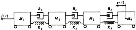
Figure P3.2
(b) Determine the transfer function Y(s)/F(s).
(c) Determine the phase-variable canonical vector form of this system.
3.3. (a) For the mechanical rotational system illustrated in Figure P3.3, write the differential equation relating T(t) and θ(t).
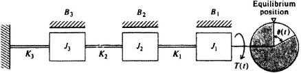
Figure P3.3
(b) Determine the transfer function θ(s)/T(s).
3.4. Figure P3.4 represents the diagram of a gyroscope which is used quite frequently in autopilots, stabilized fire control systems, and so on. Assume that the rotor speed is constant, that the total developed torque about the output axis is given by
![]()
where K′ is a constant, and that the inner gimbal’s moment of inertia about the output axis is J.
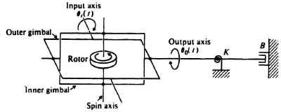
Figure P3.4
(a) Write the differential equation relating θi(t) and θ0(t).
(b) Determine the transfer fiunction θ0(s)/θi(s).
3.5. The Ward-Leonard system shown in Figure 3.12 has the constants and characteristics shown in Table P3.5. Derive the transfer function for the system θ0(s)/Ef(s).
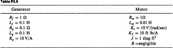
3.6. Repeat Problem 3.5 for the constants and characteristics shown in Table P3.6.

3.7. The time constant for highly inductive devices such as the armature circuit of the Ward-Leonard system shown in Figure 3.12 is usually too long for high-performance control systems. A simple technique for decreasing the time constant of such a system uses feedback, which controls the current of the inductive device. Figure P3.7 illustrates how this can be practically accomplished for a Ward-Leonard system by inserting a resistor R in series with the armature circuit. Other notations used in this diagram are the same as those used in Section 3.4. Assume that the armature current is much greater than the field current.
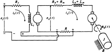
Figure P3.7
(a) Write the differential equation relating ef(t) and θ0(t).
(b) Determine the transfer function θ0(s)/Ef(s).
(c) Compare the answer to part (b) with Eq. (3.78) and show that the armature time constant has been reduced by means of feedback.
3.8. Because it is proportional to velocity, the back emf of a motor is sometimes directly used as a stabilizing voltage. Figure P3.8 illustrates a practical bridge-type circuit which can be used for this purpose. Resistors R1 and R2, which have very high resistance relative to the armature circuit resistance, are adjustable in order to obtain the desired value of eb(t). RAC represents the resistance of the armature and commutator voltage drop; RCF and LCF represent the resistance and inductance of the commutating fields, respectively. Ke, KT, J, and B have the same significance as in the text of this chapter. For the armature-controlled dc servomotor illustrated in Figure P3.8, assume that the field current If remains constant.
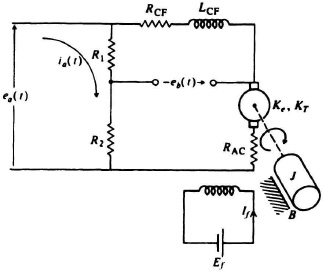
Figure P3.8
(a) Write the differential equation relating ea(t) and eb(t).
(b) Determine the transfer function Eb(s)/Ea(s).
3.9. The armature-controlled dc servomotor’s transfer function and state equations were developed in Section 3.4. Very often in practice, torque disturbances occur which adversely affect its performance. This may be due to sea waves hitting flaps of a hydrofoil, or wind gusts hitting the reflector of a tracking rada. Figure P3.9 illustrates a modification to the configuration of Figure 3.11c to illustrate a torque disturbance TU(s) addition. Let us assume for our application that we wish to have the motor velocity ![]() (s) and position θ(s) be independent of the torque disturbance TU(s). This can be accomplished as shown in Figure P3.9 by the addition of a current-feedback loop which is fed back to an added new feedback loop [consisting of an amplifier KA and B(S)] preceding the armature-controlled dc servomotor. Find the required relationship between A(s) and B(s) so that the motor velocity
(s) and position θ(s) be independent of the torque disturbance TU(s). This can be accomplished as shown in Figure P3.9 by the addition of a current-feedback loop which is fed back to an added new feedback loop [consisting of an amplifier KA and B(S)] preceding the armature-controlled dc servomotor. Find the required relationship between A(s) and B(s) so that the motor velocity ![]() (s) and position θ(s) are independent of the disturbance torquer TU(s). In practice, KaB(s) is designed to be much greater than 1 over the frequency range of interest.
(s) and position θ(s) are independent of the disturbance torquer TU(s). In practice, KaB(s) is designed to be much greater than 1 over the frequency range of interest.
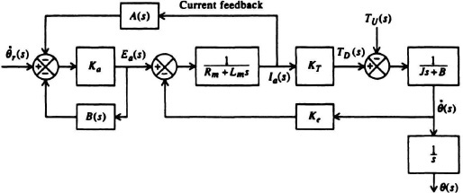
Figure P3.9
3.10. Draw the signal-flow graph for the following devices:
(a) dc generator
(b) the Ward-Leonard system
(c) two-phase ac servomotor.
3.11. Derive the transfer function C(s)/R(s) for the valve-controlled hydraulic transmission system shown in Figure 3.24 if a spring is attached between the right end of the valve control rod and some stationary reference point and viscous damping is added. Assume that the spring stiffness factor is K lb/ft and the viscous damping factor is B lb(ft/sec).
3.12. The control of paper color is a very interesting and important problem in the paper-processing industry. Figure P3.12a illustrates a functional diagram of the problem [14]. This color-control method depends on the availability of a precise, reliable, on-line colorimeter. As indicated in the diagram, dyestuff concentrations are added at various stages of the process. In this diagram, the following nomenclature is used:
f = water flow rate, in liters/minute,
α = consistencies (weight of dry fiber/weight of stock),
Vt = header tank volume,
Kv = constant at the dry end,
Vp = pipe volume,
Vs = stirred tank volume,
c = dyestuff concentration, in grams/liter,
v = machine speed, in meters/minute,
m = dyestuff flow rate, in liters/minute.
Figure P3.12b illustrates an equivalent block diagram of the color control process [14]. The factor Pr, indicated at several stages of the block diagram, is the retention factor of the dye. It varies with the concentration, with the time allowed for dyeing, and with such factors as pH, alum, resin, temperature, and dye interaction. Determine the transfer function of this system, C(s)/R(s), where
.jpg)
Figure P3.12(a)
.jpg)
Figure P3.12(b)
R(s) = dye concentration ratio = percent of dye/weight of fiber
C(s) = weight concentration of dye in the sheet at the output.
3.13. A two-phase ac servomoter has the following specifications: 115/115 V, 60 Hz, 2 phases, 4 poles; rotor moment of inertia: 0.09 oz in2, rated stalled torque 6 oz in; no-load speed: 2500 rpm; load inertia and coefficient of viscous friction are negligible. Calculate the transfer function for this servo-motor, θ0(s)/Ec(s).
3.14. It is common practice to place a gear reduction between a servomotor and the load in order to convert the high-speed, low-torque motor characteristics to a low-speed, high-torque device. Assuming a gear reduction of N : 1 and a load inertia of J2, derive the transfer function θ0(s)/Ec(s) for this system and compare it with Eq. (3.101). Use the same terminology and motor characteristics as in Section 3.4, Part E. Assume B is finite.
3.15. Based on the derivation of Problem 3.14, repeat Problem 3.13 if the load has an inertia of 0.40 oz in2, and a gear ratio of 36 : 1 is used. Assume B = 0.
3.16. Repeat Problem 3.15 with the load inertia doubled. What conclusions can you draw from your results?
3.17. A two-phase ac servomotor has the following specifications: 115/115 V, 400 Hz, 2 phases, 4 poles; rotor moment of inertia: 0.04 oz in2, rated stall torque: 2 oz in; no-load speed: 5000 rpm; load inertia: 4 oz in2 geared to the motor through a gear reduction of 9 : 1. Determine the transfer function for the overall servomotor and load. Assume the inertia of the gears is negligible, and the damping factor term B is zero.
3.18. Repeat Problem 3.17 without assuming that the gearing inertia can be neglected. Assume that the gear reduction of 9 : 1 is achieved in one gear pass and each gear has an inertia of 0.01 oz in2. What conclusions can you reach from your results?
3.19. Repeat Problem 3.17 without assuming that the gearing inertia can be neglected. Assume that the gear reduction of 9 : 1 is achieved in two gear passes of 3 : 1 each, and that each gear has an inertia of 0.01 oz in2. What conclusions can you draw from your results?
3.20. Derive the transfer function of the armature-controlled dc servomotor from its signal-flow graph.
3.21. The control system which positions the printwheel of a printer connected to a PC is illustrated in Figure P3.21.
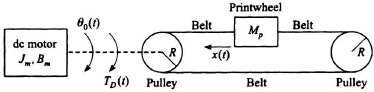
Figure P3.21
The dc motor controls the position of the printwheel and develops a torque, TD(t). The motor’s angular displacement is θ0(t), and x(t) represents the linear displacement of the printwheel. Assume that the dc motor inertia is Jm, its motor linear viscous friction is Bm, the radius of the pulley is R, the mass of the printwheel is Mp, and the belts are rigid.
(a) Determine the inertia of the printwheel.
(b) Determine the differential equation relating the developed torque, TD(t), with the angular motion of the dc motor, θ0(t).
(c) Determine the transfer function, θ0(s)/TD(s).
(d) Determine the relation between the linear motion of the printwheel, x(t), and the angular motion of the dc motor, θ0(t).
(e) Determine the transfer function, X(s)/θ0(s).
(f) Determine the transfer function of this control system, X(s)/TD(s).
3.22. Repeat Problem I3.2, Part b, for the case where Jm = J2 = JL. Determine whether system A or system B has the higher initial load acceleration.
3.23. It is desired to determine the transfer function of a two-phase ac servomotor. Its characteristics determined from its specification sheet are as follows: 115/115 V, 400 Hz, 2 phases, 4 poles, rotor moment of inertia: 10 kg m2, rates stall torque: 1000 N m, no-load speed: 100 radjsec, load inertia: 1000 kg m2 geared to the motor through a gear reduction of 10:1. Determine the transfer function for the overall servomotor and load. Assume that the inertia of the gears is negligible, and the damping factor term B is zero.
3.24. A two-phase ac servomotor (Figure P3.24) has the following parameters: 115/115 V, rotor moment of inertia: 0.02 oz in2, rated stall (developed) torque: 1 oz in, no-load speed: 4000 rpm, load inertia: 2 oz in2 geared to the motor through a gear reduction of 10 : 1. Assume the inertia of each gear is 0.01 oz in2. Determine the transfer function in its simplest form for the overall servomotor and load. Assume that the linear viscous friction term B equals zero.
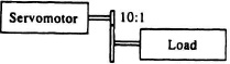
Figure P3.24
3.25. The two-phase ac servomotor shown in Figure P3.24 has the following parameters: 115/115 V, rotor moment of inertia: 0.04 oz in2, rated stall (developed) torque: 2 oz in, no-load speed: 2000 rpm, load inertia: 4 oz in2 geared to the motor through a gear reduction of 10:1. Assume the inertia of each gear is 0.01 oz in2. Determine the transfer function in its simplest form for the overall servomotor and load. Assume that the damping term B equals zero.
3.26. A two-phase ac servomotor has the following specifications: 115V/115 V, 400 Hz, 2 phases, 4 poles, rotor moment of inertia : 0.2 oz in2, rated stall torque : 4 oz in, no-load speed : 2000 rpm, load inertia of 1 oz in2 geared to the motor through a single stage of gear reduction of 3:1. Assume that the inertia of each gear in the gear reduction is 0.1 oz in2. Determine the transfer function for the overall servomotor and load. Assume that the damping factor term B equals zero.
3.27. A two-phase ac servomotor has the following specifications: 115 V/115 V, 400 Hz, 2 phases, 4 poles, rotor moment of inertia : 0.2 oz in2, rated stall torque : 8 oz in, no-load speed : 4000 rpm, load inertia of 1 oz in2 geared to the motor through a single stage of gear reduction of 3 : 1. Assume that the inertia of each gear in the gear reduction is 0.1 oz in2. Determine the transfer function for the overall servomotor and load. Assume that the damping factor term B equals zero.
3.28. Starting with Eq. (3.62), derive the state equations of the armature-controlled dc servomotor from its state-variable diagram.
3.29. Starting with Eq. (3.78), derive the state equations of the Ward-Leonard system from the state-variable diagram.
3.30. Starting with Eq. (3.101), derive the state equations of the two-phase ac servomotor from the state-variable diagram.
3.31. For the mechanical system illustrated in Figure P3.31, draw an analogous electric circuit and determine the differential equation relating the force f(t) and the position x(t).

Figure P3.31
3.32. For the mechanical system illustrated in Figure P3.32, draw an analogous electric circuit and determine the differential equation relating v1(t), v2(t), and f(t).

Figure P3.32
3.33. With the advent of modern man-machine control systems utilizing humans to perform various manual tasks, knowledge of the human transfer function is very important in order to enable the prediction of the system’s performance. Many researchers have attempted to determine the human transfer function. For manual control at relatively low frequency, the human characteristics indicate a gain K, an anticipation time constant TA, an operator’s error-smoothing lag time constant TL, an operator’s short neuromuscular delay time constant TN, and an operator’s time-delay factor D. Write the form of the human transfer function. What is the meaning of the time-delay factor D [15]?
3.34. The first untethered walk in space was conducted by Astronaut Bruce McCandless II on 7 February 1984. He use a nitrogen-propulsion hand-controlled device called the manned maneuvering unit as shown in the NASA photograph of Figure P3.34a. In this photograph, Astronaut McCandless II is a few meters away from the cabin of the Earth-orbiting space shuttle Challenger. Figure P3.34b is a rare scene of the space shuttle Challenger some 50–60m away from Astronaut McCandless which he took with a fixed camera on his helmet. Observe the robot arm-like remote manipulator system (RMS) that was first introduced in Figure 1.13.
.jpg)
Figure P3.34(a) Astronaut Bruce McCandless II, one of two mission specialists participating in a historic extra-vehicular activity, is a few meters away from the cabin of the Earth-orbiting space shuttle Challenger. This spacewalk represented the first use of a nitrogen-propelled, hand-controlled device called the manned maneuvering unit.
.jpg)
Figure P3.34(b) A fixed camera on Astronaut McCandless’s helmet recorded this rare scene of the space shuttle Challenger some 50–60 meters away during his extra-vehicular activity. (Photographs courtesy of NASA)
We wish to draw the block-diagram representation of one axis of this manual-control system where the input represents the desired position and the output represents the actual position. Assume that the human model [14] can be represented as defined in Problem 3.33, and assume that the nitrogen-propulsion hand-controlled device converts the astronaut’s control action to a force by means of proportional control, where the proportionality constant is K. It will also be assumed that the dynamics of the astronaut in converting the force of the nitrogen-propulsion hand-controlled device to a position in space can be represented as a double integration.