
5.3. SENSITIVITY
Sensitivity is a measure of the dependence of a system’s characteristics on those of a particular element. The differential sensitivity of a system’s closed-loop transfer function H(s) with respect to the characteristics of a given element K(s) is defined as
where
H(s) = C(s)/R(s).
A more meaningful definition can be obtained by rewriting Eq. (5.2) as
Equation (5.2) states that the differential sensitivity of H(s) with respect to K(s) is the percentage change in H(s) divided by that percentage change in K(s) that has caused the change in H(s) to occur. This definition is valid only for small changes. It is important to note that sensitivity is a function of frequency and an ideal system has zero sensitivity with respect to any parameter.
In order to illustrate the concept of sensitivity, consider the general control system shown in Figure 5.1a. Here K1 represents the transfer function of the input transducer, K2 represents the transfer function of the feedback transducer, and G(s) represents the combined transfer function of an amplifier, stabilizing network, motor, and gear train in the forward part of the feedback loop.
The overall system transfer function H(s) is given by
Let us now determine the sensitivity of the overall system transfer function with respect to changes in K1, K2 and G(s).
A. Sensitivity of H(s) with respect to K1
This is
![]()
where
![]()
Therefore,
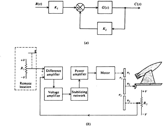
Figure 5.1 (a) A representative control system. (b) An automatic positioning system for a missile launcher.
B. Sensitivity of H(s) with respect to K2
This is
![]()
where
![]()
Therefore
![]()
For frequencies where K2G(s) ≫ 1, this reduces to
C. Sensitivity ot H(s) with respect to G(s)
![]()
where
![]()
Therefore,
The results obtained in Eqs. (5.5), (5.6), and (5.7) are quite interesting. The symbols K1 and K2 represent input and feedback transducers, respectively, and Eqs. (5.5) and (5.6) illustrate that they are very critical. Any changes in their characteristics are directly reflected in an overall system transfer-function change. Elements used for K1 and K2 must, therefore, possess precise and stable characteristics with temperature and time. Equation (5.7) shows that the sensitivity of the overall system transfer function with respect to G(s) is divided by 1 + K2G(s). From a sensitivity viewpoint, it appears desirable to design K2G(s) to have as large a value as possible. However, it need not be very precise.
It is also important to recognize that because sensitivity is a function of frequency, we should think of systems as being sensitive or insensitive only over certain frequency bands. In this example, K2G(s) is a function of frequency and will be large over only a limited range of frequencies. Therefore, H(s) is insensitive to G(s) only over a certain range of frequencies. This point is further illustrated in Problems 5.1 through 5.14.
Let us now try to extend the results derived in this section in order to determine qualitatively the requirements of the various elements shown in the simple missile launcher positioning device of Figure 5.1b. In this system R1 R2, ± V, and the difference capability of the difference amplifier must all be precise. The gain characteristics of the difference amplifier, voltage, stabilizing network, power amplifier, and motor need not be precise. Any changes in the characteristics of these elements will be divided by 1 + K2G(s). Let us now consider the gear train, which is composed of three gears n1 n2, n3. It is assumed that gears n2 and n3 have the same number of teeth and each has 10 times as many teeth as gear n1. The output is taken off gear n2. The prime purpose of gear n3 is to enable the output transducer to be coupled off another shaft. Gear meshes can result in system errors because the tooth space exceeds the thickness of an engaging tooth. This phenomenon is commonly referred to as backlash. It can be measured by holding one gear fast and observing the amount of motion in the other gear. Figure 5.1b denotes the backlash between gears n1 and n2 as e1 and that between n2 and n3 as e2. A sensitivity analysis shows that the error produced by backlash e1 is reduced by 1 + K2G(s), whereas the error produced by backlash e2 is coupled into the feedback element K2 and, therefore, its effect is seen through ![]() (s). Therefore, there is a need for precision gearing for n2 and n3, but not for n1. Chapter 10 illustrates that backlashes at e1 and e2, however, are very important from a stability viewpoint. From a sensitivity viewpoint, however, the backlash at e1 is not as critical as that at e2.
(s). Therefore, there is a need for precision gearing for n2 and n3, but not for n1. Chapter 10 illustrates that backlashes at e1 and e2, however, are very important from a stability viewpoint. From a sensitivity viewpoint, however, the backlash at e1 is not as critical as that at e2.