
7.4. PROPORTIONAL-PLUS-INTEGRAL-PLUS DERIVATIVE (PID) COMPENSATORS
PID compensators are another form of compensation frequently used in control systems, especially in the industrial process control field. They are very popular in the industrial process control field due to their robust (insensitive) performance over a wide range of operating conditions including plant uncertainty, parameter variation, and external disturbances. Robust control is presented in Section 8.10 of Chapter 8.
Assuming that the input to the PID compensator is e(t) and its output is u(t), the equation defining the operation of the PID compensator is given by:
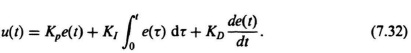
Figure 7.16 illustrates a block diagram representation of Eq. (7.32). The transfer function of the PID compensator is obtained as follows:
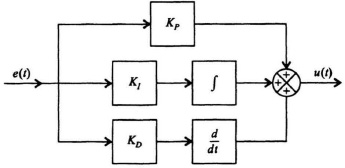
Figure 7.16 PID compensator block-diagram representation of Eq. (7.32).
The resulting transfer function of the PID compensator, Gc(s), is given by
Figure 7.17 illustrates a block diagram representation of Eq. (7.35). Observe from Eqs. (7.32) and (7.35) that the PID compensator provides a proportional term, an integration term, a derivative term, as its name implies.
Very often, only a portion of the very general PID compensator is used. For example, if KD = 0, then we have
which is denoted as the proportional plus integral, or PI, compensator. If KI = 0, then we have
which is denoted as the proportional plus derivative, or PD, compensator. This was illustrated previously in Figure 7.14.
To consider the design of a PID compensator, let us reconsider the transfer function of Gc(s) given by Eq. (7.35):
This can be rewritten as
or,
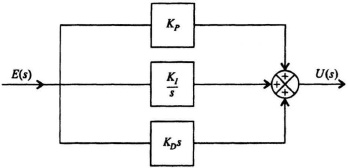
Figure 7.17 PID compensator block diagram representation of Eq. (7.35).
![]()
Factoring the numerator of Eq. (7.40), and assuming the quadratic factors as two real zeros, we obtain the following:
The very pleasing result of Eq. (7.41) is that the PID compensator results in two zero factors which can be located anywhere in the left-hand of the s-plane, in addition to the pole at the origin. We know from the analysis in Sections 7.2 and 7.3 that a zero factor provides a phase lead and aids in the compensation of a control system. In particular, as illustrated in Figure 7.14b, a PD is equivalent to one zero factor (which the rate feedback compensator also provides and is illustrated in Figure 7.14a). With the complete PID compensator, two zero factors are provided for compensation, in addition to the pole at the origin.
Applications of PI, PD, and PDI compensators are illustrated throughout this book for compensating control systems. These techniques are very useful for compensation of control systems in addition to the phase-lag, phase-lead, and phase-lag–lead networks illustrated in Section 7.2, and minor-loop rate feedback illustrated in Section 7.3.