
4.5. WHAT IS THE BEST DAMPING RATIO TO USE?
A very important question to answer before leaving this chapter is the best value of damping ζ to choose for a control system. Section 4.2 had indicated that most practical systems are usually designed to be somewhat underdamped. This will be discussed further in Section 5.6 from the viewpoint of various performance criteria. This section will present general guidelines for the selection of damping for three specific cases:
A. Design of a Control System for General Applications
Suppose it is desired to design a linear control system for general applications. It is assumed that the designer does not know the final application of the control system. The selection of the damping ratio for such a general application requires a tradeoff between maximum percent overshoot and the time where the peak overshoot occurs, tp. A smaller damping ratio decreases tp (which is desirable), but it increases the maximum percent overshoot (which is undesirable). Final choice of the damping ratio is subjective. It has been my experience that the damping ratio range is usually selected between 0.4 and 0.7 for this general case. It is important to note that Chapter 5, Section 5.8 on “The ITAE Performance Criterion for Optimizing the Transient Response” shows that the damping needed to minimize the integral of time times the absolute value of the error (ITAE) performance criterion is 0.7 for second-order systems.
The selection of the best damping ratio should not be restricted to the limitations imposed by linear system theory. If we analyze Figure 4.4, we recognize that the best choice of the damping ratio is between 0.4 and 0.7 from the viewpoint of linear system theory (tradeoff between maximum percent overshoot and the time at which it peaks). However, it is important to emphasize that a linear system is not the best choice for optimizing transient responses. A nonlinear system can be designed to give a better transient response than a linear system, and an adaptive control system can be designed to give a better transient response than a nonlinear system [1]. Adaptivity refers to a system where the damping factor varies continually with time as a function of the system error, and the damping factor “adapts” to the system error.
Consider the three transient responses illustrated in Figure 4.8 to a unit step input: a linear control system, a nonlinear control system, an adaptive control system. The linear control system’s transient response is representative of a second-order system having a damping ratio of 0.4 and an undamped natural frequency of 1 rad/sec.
We can improve this linear control system’s transient response with the nonlinear system’s response illustrated which can be obtained with the configuration shown in Figure 4.9 where the amplifier gain K is a function of the control-system error [1]. Qualitatively, the amplifier gain K is set at a relatively high value for very large errors (and the resulting damping factor will be very low), and K is set at a much smaller value for small errors (and the resulting damping factor will be much higher). It is theoretically possible for such a system to have the transient response of A-B-C-D shown in Figure 4.8, where the gain is set at a very high value from 0 to t1 and it is set at a much lower value from t1 to t2. The damping factor might be designed for 0.1 from A to B, and it might be designed to be critically damped from B to C. (The gain would be switched at point B.) Such a system has the advantage that it responds to its steady-state value quicker than the linear control system, and without any overshoots.

Figure 4.8 Comparison of transient response of a linear control system (where ζ = 0.4 and ωn = 1), a hypothetical nonlinear control system, and an adaptive control system to a unit step.
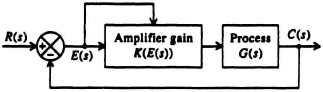
Figure 4.9 A control system where the amplifier gain is a function of the error.
We can improve the transient response of the nonlinear control system shown with an adaptive control system where the amplifier gain, in the configuration of Figure 4.9 is continually varied as a function of time (not just two gain settings as in the nonlinear control-system case). Therefore, the damping ratio of this configuration “adapts” to the error present continuously as a function of time. For example, near point A, it is theoretically possible for the damping ratio to be set at 0.01 (or undamped), and then it can be gradually increased to unity just below point E. In practice, the control-system engineer must design this adaptive control system very carefully and take into account the inertias and the dynamics of the system—otherwise, overshoots and/or undershoots can occur which might make this system’s transient response worse than the nonlinear and linear control-system configurations. Reference 1 illustrates how to design such an adaptive control system and achieve its full benefits.
B. Design of a Very Accurate Linear Control System
Let us assume that it is necessary to design an extremely accurate linear control system whose steady-state errors to position and velocity inputs are extremely small (e.g., to be used for navigation purposes). For such a system, the transient response is not the primary performance criterion to optimize, but minimum steady-state error is the major objective. In Chapter 5, it is proved that the steady-state error of a second-order control system to a velocity input of unit magnitude is given by 2ζ/ωn [reciprocal of Eq. (5.37)]. In such a case, it is very important to design the damping ratio to be as small as possible because the steady-state error is proportional to the damping ratio. Values less than 0.1 are not unreasonable for such applications, and the disadvantage of waiting for the relatively long transient response times to settle out must be tolerated.
C. Design of a Slowly Responding Linear Control System
Some applications require a very slow response of the linear control system. An example of this might be an elevator, or a platform that is part of a simulator used to train sailors in the diving and control functions of a submarine. For these applications, which are usually found where people are located on a platform that the control system is positioning (such as found in trainers) or in simulation of slowly varying processes, the control system’s damping factor is selected to try to duplicate the dynamics of the vehicle or system that is being simulated. Damping ratios greater than 1 are usual in these applications, and damping ratios as high as 2 may be reasonable.
From the three control-system cases considered, we have justified damping ratios from 0.01 (for part of the transient response in the case of the adaptive control system) to values up to 2.0. In conclusion, the damping ratio selected is determined by the particular control system’s application.