
Now we can hit the Make Tx button and it will also be available in
the Texture palette.
Before the export, be sure to take a look at the results. Fill the
actual layer with the generated displacement map by hitting the
FillLayer button.
If everything is fine, export it using the Export button on the Tex-
ture palette.
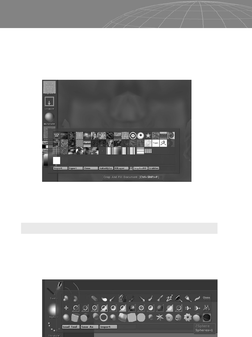
Modeling with ZSpheres
With ZBrush you can also create a base mesh instead of importing
one from a 3D package. ZSphere is a tool that allows you to create a
multi-limbed exoskeleton that is pretty easy to adjust and manipu-
late. ZSphere is usually the last tool (the red ball) at the right end of
the palette (by default).
266
Chapter 11 – Introduction to ZBrush
Figure 11-61
Figure 11-62

Click and drag to place a ZSphere on the canvas. Pressing T puts us
in Edit mode, and the procedures for rotating, editing, and so forth
are the same as for any other 3D tool (imported or not). As we
move the cursor over the ZSphere in Edit mode, notice that a little
circle appears as we move the cursor and a line is drawn to link it to
the center circle. When the cursor circle is green, it means it’s in a
perpendicular position, which is perfect for adding a new ZSphere;
click and drag to insert a new ZSphere. Exit Draw mode in order to
use the Move, Rotate, and Scale tools to perform modifications to
the whole ZSphere structure.
Press A to see a preview of how the mesh will look when converted
to a polymesh. Press A again to turn it off. Notice that any modifica-
tion we make will be updated next time we activate the wireframe
preview.
267
Chapter 11 – Introduction to ZBrush
Figure 11-63
Figure 11-64

With ZSpheres you can perform three basic operations regarding
the creation process:
4
Add — To add a ZSphere to a limb, click on it with Draw mode
activated.
4
Remove—ToremoveaZSphere,holdAltandclickthe
ZSphere with Draw mode activated.
4
Add Magnet — To add a ZSphere magnet, choose a sphere and
with Draw mode activated, Alt+click the gray part of the limb.
Figure 11-65 shows four segments in the image on the left. The
right image shows the same object after two ZSpheres have been
deleted.
For this quick magnets example we create two symmetrical lateral
horns for our character with ZSpheres.
268
Chapter 11 – Introduction to ZBrush
Figure 11-65
Figure 11-66

In Figure 11-67 the image on the left shows our preview mesh.
When we Alt+click in Draw mode and activate the gray part of the
horn, the ZSphere becomes a ZMagnet, and we can see the influ-
ence of the magnet when we activate the Preview mode (press the
A key).
We can also carve the mesh using ZSpheres to apply a subtract
effect on the mesh, as shown in Figure 11-68.
Once we’ve finished creating our ZSphere structure, we can press A
again for a final preview and then hit Make Polymesh 3D under the
Tool menu. A new copy of the polymesh will be created so you can
clean the canvas (Ctrl+N), redraw the new copy, and start editing.
269
Chapter 11 – Introduction to ZBrush
Figure 11-67
Figure 11-68: Left, the ZSphere is placed. Center, the ZSphere is pushed
back until it enters the root ZSphere. Right, using Preview mode we can see
that this process created a hole in our mesh that is topologically correct.
..................Content has been hidden....................
You can't read the all page of ebook, please click here login for view all page.