
Doo-Sabin Surfaces (1978)
Daniel Doo and Malcom Sabin adapted Chaikin’s polygon refine-
ment technique for the bi-quadratic uniform B-spline and developed
a new procedure for surface generation. Doo-Sabin is a dual approxi-
mating scheme for meshes of arbitrary topology. All the vertices
have a valence of 4 after the first subdivision refinement.
Catmull-Clark Subdivision (1978)
The algorithm proposed by Edward Catmull and Jim Clark is the
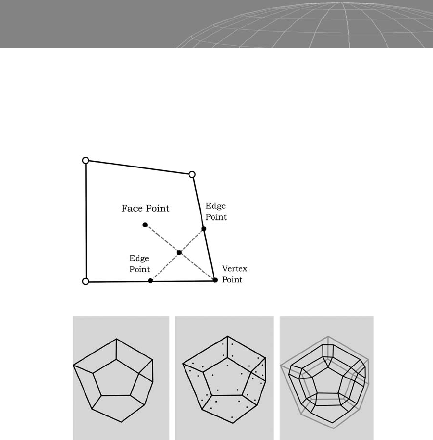
most widely known and used. When the mesh is subdivided, new
vertices (face points) are placed at the center of each unrefined face
and in the center of each unrefined edge, and then new edges are
created to connect these new vertices. It’s an approximating primal
scheme.
46
Chapter 3 – Polygon Subdivision
Figure 3-6
Figure 3-7: Left, an unrefined mesh. Center, vertices placed by the
Doo-Sabin method and then connected. Right, the subdivided shape is
shown in black and the original, unrefined mesh is shown in gray.

These are the steps of Catmull-Clark subdivision:
1. The face points are created by averaging positions of the poly-
gon’s unrefined vertices.
2. Edge point locations are calculated by averaging the center
point of an unrefined edge and the locations of the two new
adjacent face points.
3. The positions of the old vertices are reconfigured using the
following equation:
47
Chapter 3 – Polygon Subdivision
Figure 3-8: Variable Q represents the average of the new vertices (face
points) surrounding the unrefined vertex. Variable R represents the average
of the edge’s midpoints that share the unrefined mesh. Variable S is the
original, unrefined mesh. Variable n is the number of edges that share the
old unrefined vertex.
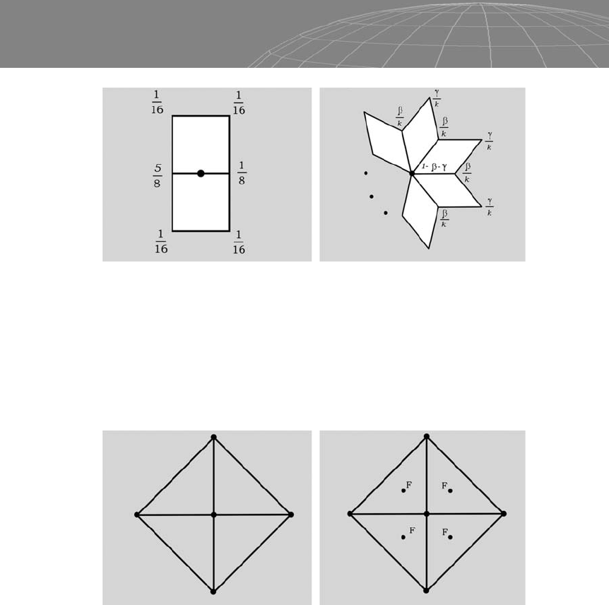
Figure 3-9: Left, a mask scheme for an edge vertex. Right, a mask for a face
vertex.
Figure 3-10: Left: a mask for boundary odd vertices. Right, a mask for even
vertices.
Catmull-Clark is an excellent scheme for ordinary vertices (valence
of 4, quads) but also works with valences that are greater than or
less than 4.
The following figures demonstrate the Catmull-Clark subdivi-
sion scheme.
48
Chapter 3 – Polygon Subdivision
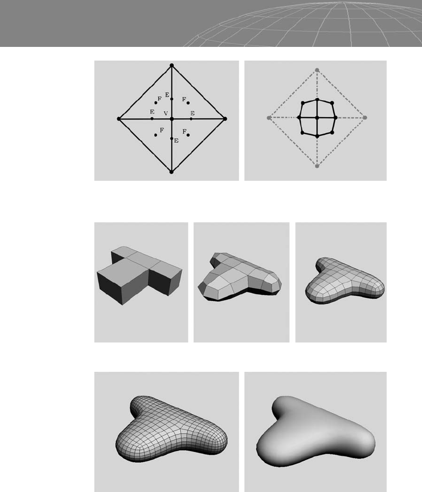
Figure 3-11: Left, a mask for extraordinary vertices. Right, a mask for interior
even vertices.
Figure 3-12: An unrefined cube primitive seen from the top view. The face
points are generated and placed using the Catmull-Clark subdivision
method.
49
Chapter 3 – Polygon Subdivision
Figure 3-13: New vertex points (F) generated from the (E) points (see Figure
3-11). These new vertices are then connected, forming the subdivided shape.
Figure 3-14: Subdivision example.
Figure 3-15: Refinement of subdivision example.
..................Content has been hidden....................
You can't read the all page of ebook, please click here login for view all page.