
Extruding
The Extrude tool described here refers to extrusion of the poly-
gon’s sub-elements, like a face, edge, or vertex. Face extrusion is
oriented by its element normal, generating new faces along the side
of the origin extrusion and extruded face. Edge and vertex extru-
sion are similar to face extrusion. These processes extrude the
selected sub-object, obeying the topology and using the object’s
normal as the direction reference.
26
Chapter 2 – Polygon Operations
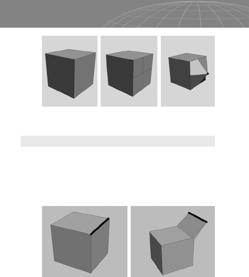
Figure 2-7: Here we have made a “+” cut in the face of a box and pulled the
vertex forward.
Figure 2-8: Edge extrusion.

Figure 2-11 shows extrusion operations combined with rotation
operations.
Most 3D packages give you several options for extrusion, including
group extrusion, extruding by polygon, and extruding by local
normal.
With the Extrude by Group option, you extrude the selected
polygons as a group.
27
Chapter 2 – Polygon Operations
Figure 2-9: Vertex extrusion.
Figure 2-10: Face extrusion.
Figure 2-11: Face selected, extruded, rotated a bit, extruded again, rotated, and
extruded. Note that you can extrude as many times as you wish, and every time you
extrude the face, new edges stay where you stopped the last extrusion.
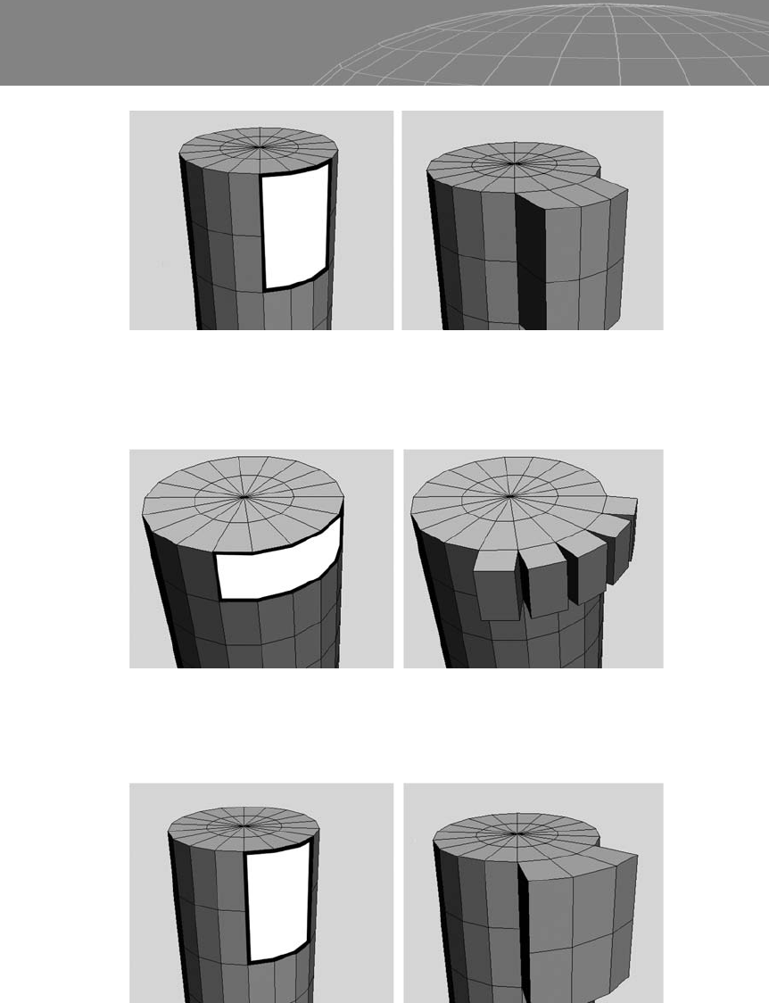
With the Extrude by Polygon option, the polygons will be extruded
independently from each other.
With the Extrude by Local Normal option, the polygons follow the
local normal of each polygon, but they stay together as a group.
28
Chapter 2 – Polygon Operations
Figure 2-12: Extruding group.
Figure 2-13: Extruding by polygon.
Figure 2-14: Extruding by local normal.
..................Content has been hidden....................
You can't read the all page of ebook, please click here login for view all page.