

It’s important to remember that it is very common to have two or
more ways to do the same thing in 3D. This is really great because
it allows you to choose the best (and possibly quicker) way to reach
the desired result.
Holes in Curved Surfaces
Another inorganic modeling technique is making a hole in a curved
polygonal surface. Figures 3-78 to 3-82 demonstrate this process.
The first step is to align the edges to sketch a square and then
cut as shown at the center and right.
75
Chapter 3 – Polygon Subdivision
Figure 3-76
Figure 3-77

Then weld excessive vertices to clean up the mesh, select the poly-
gons around the hole area, and delete them. With the hole defined,
cut around it to rebuild the adjoining polygons. There are too many
triangles here, which add unnecessary tension. Remove the edges
to form the mesh as shown on the right in the following figure.
With the correct topology established around the hole, you can cut
using the same polygon loop to improve the local tension and get a
nice, smooth hole in curved surfaces. Notice that this is a perfectly
round hole, but if you wish you can move the vertices around to
modify its shape.
76
Chapter 3 – Polygon Subdivision
Figure 3-78
Figure 3-79
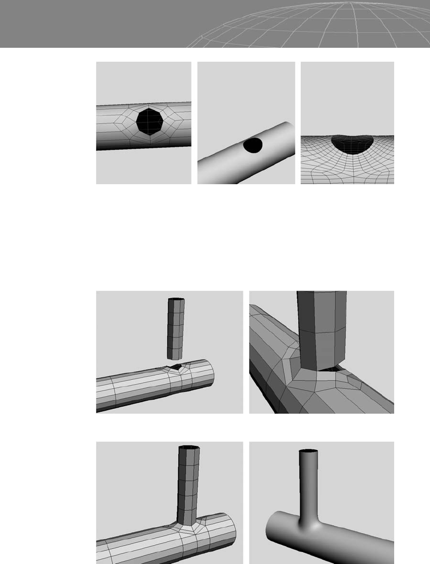
Now that the hole in the curved surface has the correct topology,
you can attach another piece, as shown in Figures 3-81 and 3-82
below. Pay attention to the number of vertices of the objects you are
attaching. Notice that in this exercise both the hole and the new cyl-
inder have eight vertices to be merged.
77
Chapter 3 – Polygon Subdivision
Figure 3-80
Figure 3-81
Figure 3-82
..................Content has been hidden....................
You can't read the all page of ebook, please click here login for view all page.