

Layers
Since version 5, 3ds Max has had a nice layer system that allows the
user to easily manage the objects in a scene. It is accessed with the
Layer button .
There are a number of buttons at the top of the Layer window.
From left to right these buttons are:
Create a New Layer: Creates a new layer. To rename the new
layers, double-click on the layer’s name.
Delete Highlighted Empty Layers: Delete empty selected
layer.
Add Selected Objects to Highlighted Layers: Add the selected
object to the selected layer. When you add new objects to an
empty layer, there will be a plus sign preceding the layer label.
This indicates that the layer has objects inside and can be ex-
panded.
Select Highlighted Objects and Layers: Select everything in-
side the selected layer.
Select Highlighted Object’s Layers: Select the layer to which
the selected object belongs.
Hide/Unhide All Layers: Hide and Unhide Layers toggle.
Freeze/Unfreeze All Layers: Freeze and Unfreeze layers toggle.
349
Appendix A – 3ds Max Polygonal Modeling Quick Start Guide
Figure A-16: The Layer window.
Figure A-17

Pivot
Pivot can be found in the Hierarchy Panel tab. Pivots are treated
like subobjects. To edit the pivot position and rotation you must
access one of the options available under the Adjust Pivot rollout.
Affect Pivot Only will allow you to manually adjust the pivot point. It
also offers a few other options to automatically align the pivot point
to the object, center the pivot point to the object’s center, or world
alignment.
Display Panel
In the Display Panel you will find options for hiding, unhiding, and
making the selection of specific objects unavailable (freezing), as
well as other display properties.
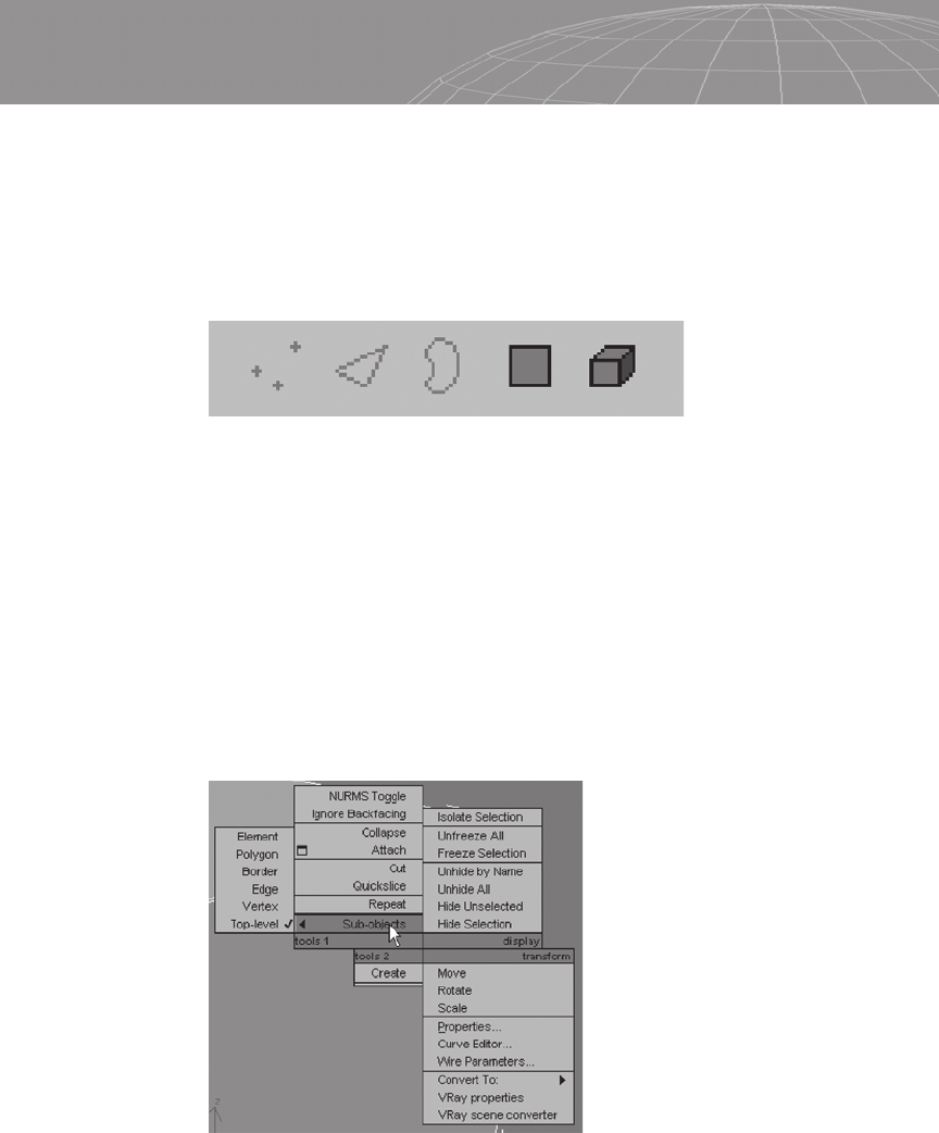
Subelements Structure
3ds Max has two ways to deal with meshes: Edit Mesh and Edit
Poly. The main differences are that Edit Mesh splits the polygons
into triangular faces and has a subobject foundation that is a bit
different.
In Edit Mesh we have Vertex, Edge, Face, Polygon, and Ele-
ment options. In Edit Poly we can work with Vertex, Edge, Border,
Polygon, and Element options. Additionally, some tools are available
only in Edit Mesh mode or only in Edit Poly mode. Most of the
350
Appendix A – 3ds Max Polygonal Modeling Quick Start Guide
Figure A-18
improvements in the modeling part of 3ds Max were made to Edit
Poly and provide many benefits for polygonal modeling. To simplify
the process of understanding polygonal modeling in 3ds Max, this
quick start guide only presents the Edit Poly functions.
The subelements structure in Edit Poly mode is shown in Fig-
ure A-19.
The vertex subelement can be accessed through the quad menu (by
right-clicking) or by pressing the 1 key.
The edge subelement can be accessed through the quad menu
(by right-clicking) or by pressing the 2 key.
The border subelement can be accessed through the quad menu
(by right-clicking) or by pressing the 3 key.
The polygon subelement can be accessed through the quad
menu (by right-clicking) or by pressing the 4 key.
The whole mesh element can be through the quad menu (by
right-clicking) or by pressing the 5 key.
351
Appendix A – 3ds Max Polygonal Modeling Quick Start Guide
Figure A-19: The Vertex, Edge, Border, Polygon, and Element options.
Figure A-20
Editing Polygons
The tools for editing polygons in 3ds Max are located in the Modi-
fier Panel. There are more buttons than your resolution can
probably display at one time, so if you feel that something is miss-
ing, click and hold in an empty area of the Modifier Panel, and scroll
down to find the other buttons.
Cut
You can cut polygons in 3ds Max in several different ways. When
you point the cursor over a vertex, the cursor changes to to
indicate you are over a vertex and the cut will start precisely over
the vertex.
When you position the cursor over an edge, the cursor will be
changed to to indicate the cut will start from the edge the cur-
sor is over.
When you position the cursor over a polygonal face, the cursor
changes to to indicate that the cut will start from the point of
the face the cursor is over.
3ds Max indicates the path of the cut in a real-time display.
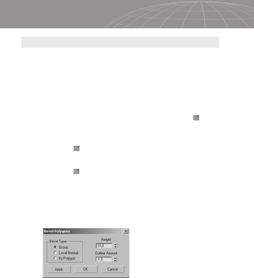
Bevel
Bevel functions in 3ds Max have three main parameters to define,
as shown in Figure A-21.
The Bevel Type sets how the bevel will work: by group, local nor-
mal, or polygon. This works like extrude, which was discussed in
Chapter 2. Height determines how much the polygon will be
extruded before the beveling action. Outline Amount specifies how
much the face will be scaled down after the extrusion.
352
Appendix A – 3ds Max Polygonal Modeling Quick Start Guide
Figure A-21: Bevel Polygons window.
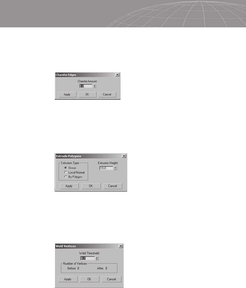
Chamfer
Chamfer in 3ds Max has one option, which determines the size of
the edge chamfer. Note that chamfer commands exist for both edges
and vertices, and they perform differently.
Extrude
Extrude has two main parameters: Extrusion Type (as discussed in
Chapter 2) and Extrusion Height, which determines the height to
which the polygon will be extruded.
Weld
The Weld Threshold option in the Weld Vertices window deter-
mines the range of vertices that will be picked and merged together.
353
Appendix A – 3ds Max Polygonal Modeling Quick Start Guide
Figure A-22: Chamfer Edges window.
Figure A-23: Extrude Polygons window.
Figure A-24: Weld Vertices window.
..................Content has been hidden....................
You can't read the all page of ebook, please click here login for view all page.