
Appendix A
3ds Max Polygonal
Modeling Quick Start
Guide
3ds Max allows the user to customize the user interface completely,
changing shortcuts, panels, toolbars, colors, and many other func-
tions to improve the workflow. In this appendix, we discuss how you
can customize 3ds Max.
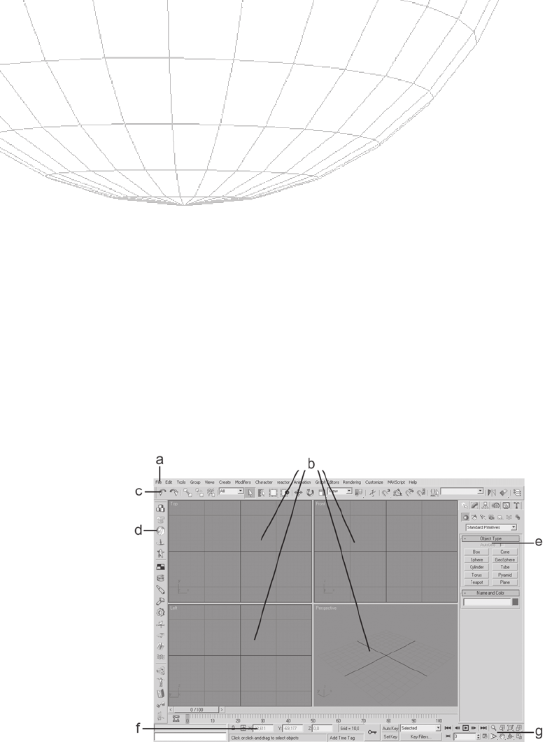
The letters in Figure A-1 correspond to the list below the
figure.
a - Menus: 3ds Max main menus contain options for loading, sav-
ing, importing, and many other functions found in the
Command Panel.
339
Figure A-1: The 3ds Max user interface.

b-Viewports:3dsMaxworkarea.
c - Toolbar: The main area where you can find basic tools for ob-
ject manipulation.
d - Docked toolbar: Toolbar that can be attached to the main win-
dow or used as a floating toolbar. By default 3ds Max has a
Reactor docked toolbar.
e - Command Panel: Probably the most used panel in 3ds Max.
This is where most of the options related to modeling in 3ds
Max will appear.
f - Lower interface bar: Contains controls for animation.
g - Navigation and playback controls: Controls that are used to
move around in 3ds Max and play the animation.
Customization
To customize your interface in 3ds Max, choose Customize from the
main menu and select Customize User Interface. This will open a
new window filled with options that allow you to change shortcuts
and preferences, such as navigation hotkeys, tools, and menus.
340
Appendix A – 3ds Max Polygonal Modeling Quick Start Guide
Figure A-2: Customize User Interface window.

Assigning Hotkeys
The Keyboard tab in the Customize User Interface window refers to
the keyboard shortcuts. To assign a shortcut, make a selection in
the Group list box, then choose from the Category list box. Place
the desired shortcut in the Hotkey box and press Assign.
Creating a New Toolbar
In 3ds Max it is possible to create a new toolbar (or “shelf” as it’s
called in Maya) on which you can place an icon for quickly accessing
tools you use often.
To create a new toolbar, go to Customize | Customize User
Interface and select the Toolbars tab. When you press the New but-
ton, a new toolbar will be created. For this demonstration, name it
“Modeling1,” as shown in Figure A-3, and click OK. A small window
will appear; click on an action in the list and drag it inside the
toolbar.
Now our new toolbar has three tools: Cap Border, Bevel, and Break.
If the action you selected does not have a proper icon, it will appear
as text. The text will be gray when it is not available and black when
it is available. If you prefer, you can create your own icons for your
toolbar.
Creating Icons
Icons to be used inside 3ds Max must be in one of two resolution
formats: 24x24 pixels and 16x16 pixels, plus versions in 24x24 and
16x24 pixels for a black and white mask. This means that 3ds Max
will read the image file once for the color that will appear and then
341
Appendix A – 3ds Max Polygonal Modeling Quick Start Guide
Figure A-3: New Toolbar window.
Figure A-4: Modeling1 toolbar.
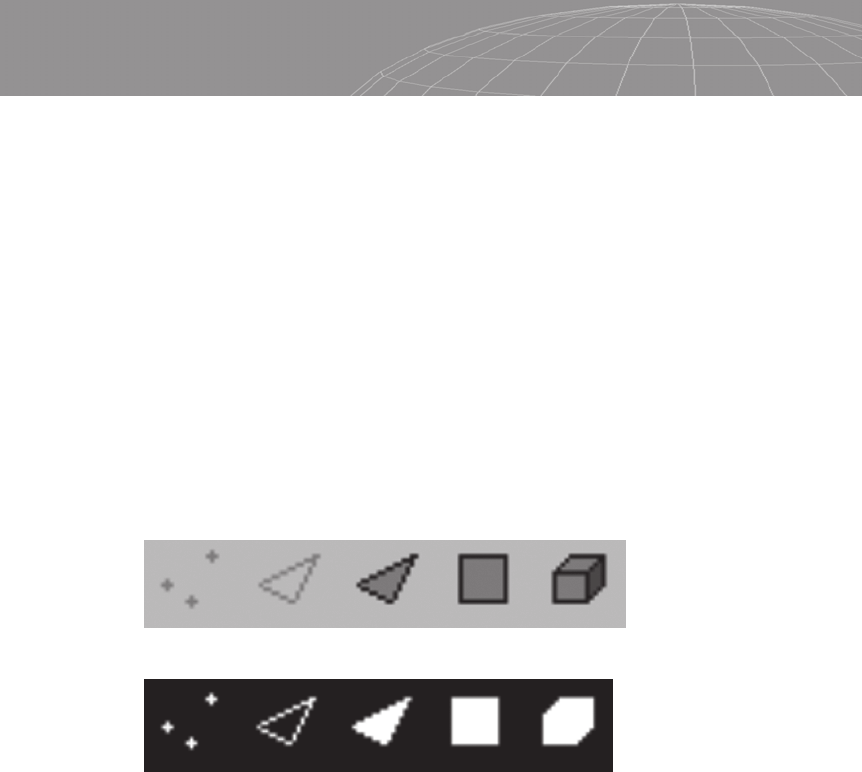
read the black and white image file to set the transparency of the
icon.
It is recommended that you save the icons as bitmap (.bmp)
files.
Be sure to correctly name your icon file. As an example, let’s
use “IconName” for our new icons:
IconName_24i.bmp — for the 24x24-pixel color icon
IconName_16i.bmp — for the 16x16-pixel color icon
IconName_24a.bmp — for the 24x24-pixel mask icon
IconName_16a.bmp — for the 16x16-pixel mask icon
Notice that color icons have an “i” after the number of pixels and
the mask, or alpha, has an “a” to indicate it’s the transparency ori-
entation reference. The black represents what will be invisible and
the white indicates what will be visible. Grayscale tones indicate
semi-transparency.
You can also make new icons and place them side by side to create a
set of four 24x24 icons that is 96x24 pixels.
When you’re done with the new icons, place them inside the
discreet and Icon folders inside the UI folder on the root 3ds Max
installation folder.
If you have questions about the general aspects of 3ds Max
icons, be sure to check the UIIcons folder and take a closer look at
the examples there.
Now we can place the icons inside our toolbar. Right-click on
the text you want to change to an icon and choose Edit Button
Appearance. Select the Image Button radio button, and in the Group
list box select the set of icons you’ve created and then choose the
icon.
342
Appendix A – 3ds Max Polygonal Modeling Quick Start Guide
Figure A-5: Icons for the color mode example.
Figure A-6: Icons for the mask/alpha example.

Be sure to take a look at the icons that discreet provides; there are a
lot of icons for modeling that aren’t used.
General Performance
To change viewport parameters such as the vertex dot size or
backface culling at primitive creation, and to set the OpenGL or
Direct3D properties of your graphic 3D card, go to Customize |
Preferences in the Viewport tab.
To manage other viewport properties, right-click the viewport’s
label and select the Rendering Method tab. The main properties
that can be changed for modeling purposes in the Rendering
Method tab are Rendering Level and Rendering Options. Rendering
Level changes the aspect of surface display like smooth highlights,
facets, etc. Rendering Options lets you select and unselect the
Force Two Sided option, which relates directly to the display of
faces with flipped normals.
If you mess up the UI at any time, go to the menu item Custom-
ize | Load Custom UI Scheme and select DefaultUI.ui file. If you
are satisfied with the UI scheme and want to preserve it, go to Cus-
tomize | Save Custom UI Scheme and then select Customize |
Lock UI Layout to prevent any accidental changes to the UI.
343
Appendix A – 3ds Max Polygonal Modeling Quick Start Guide
Figure A-7: Edit Macro Button window.
..................Content has been hidden....................
You can't read the all page of ebook, please click here login for view all page.