
Subdivision and Wire Tension
Most 3D applications use Catmull-Clark subdivision. It is the indus-
try standard for dealing with polygonal geometry. As this
subdivision algorithm works best with meshes with ordinary verti-
ces (valence 4, quads), effort has been made to keep the methods
and techniques quad as much as possible. When that’s not possible,
non-quad polygons are used in areas of less deformation.
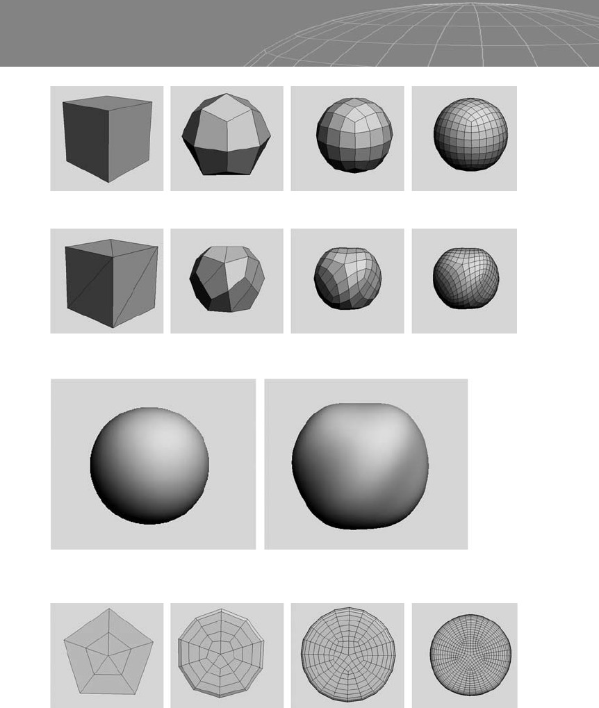
The difference between a cube polygon with six faces (quad)
(see Figure 3-30) and a cube with 12 faces (tri) (see Figure 3-31) is
very clear after some Catmull-Clark subdivision: The edges across
the tri faces generate unnecessary tension, giving a deformed look
to the cube during the subdivision process.
55
Chapter 3 – Polygon Subdivision
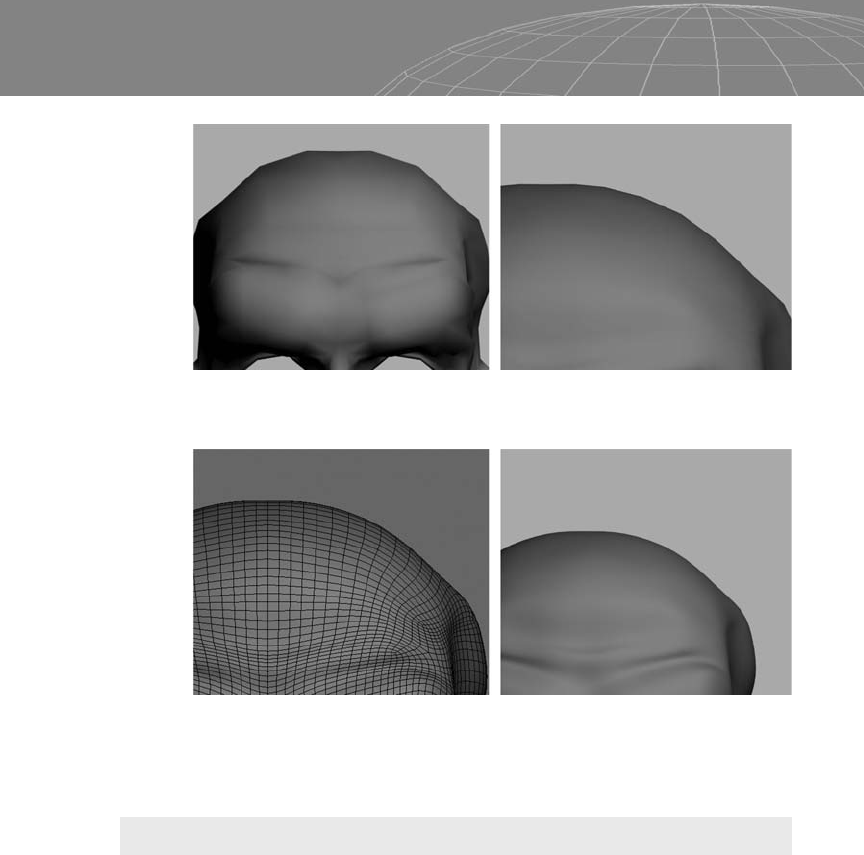
Figure 3-28: Left, bad continuity. Note the facets at the top of the head.
Right, after one step of subdivision. There are still some artifacts.
Figure 3-29: The same object with two levels of subdivision. We can almost
see the facets in wireframe, but at render time they are nearly imperceptible.
56
Chapter 3 – Polygon Subdivision
Figure 3-30
Figure 3-31
Figure 3-32: Left, final result of cube subdivision of six quad faces. Right, final result of
cube subdivision of 12 tri faces.
Figure 3-33: Subdivision process of a pentagon cylinder mesh.
..................Content has been hidden....................
You can't read the all page of ebook, please click here login for view all page.