12.7 An Application to Alternating-current (ac) Circuits
Basic Circuit with Resistance, Inductance, and Capacitance • Impedance • Phase Angle • Phasor • Resonance
We now show an application of complex numbers in a basic type of alternating-current circuit. We show how the voltage is measured between any two points in a circuit containing a resistance, a capacitance, and an inductance. This circuit is similar to one noted in earlier examples and exercises in this chapter.
A resistance is any part of a circuit that tends to obstruct the flow of electric current through the circuit. It is denoted by R (units in ohms, ) and in diagrams by ![]() , as shown in Fig. 12.21. A capacitance is two nonconnected plates in a circuit; no current actually flows across the gap between them. In an ac circuit, an electric charge is continually going to and from each plate and, therefore, the current in the circuit is not effectively stopped. It is denoted by C (units in farads, F) and in diagrams by
, as shown in Fig. 12.21. A capacitance is two nonconnected plates in a circuit; no current actually flows across the gap between them. In an ac circuit, an electric charge is continually going to and from each plate and, therefore, the current in the circuit is not effectively stopped. It is denoted by C (units in farads, F) and in diagrams by ![]() (see Fig. 12.21). An inductance is basically a coil of wire in which current is induced because the current is continually changing in the circuit. It is denoted by L (units in henrys, H) and in diagrams by
(see Fig. 12.21). An inductance is basically a coil of wire in which current is induced because the current is continually changing in the circuit. It is denoted by L (units in henrys, H) and in diagrams by ![]() (see Fig. 12.21). All these elements affect the voltage in an ac circuit. We state here the relation each has to the voltage and current in the circuit.
(see Fig. 12.21). All these elements affect the voltage in an ac circuit. We state here the relation each has to the voltage and current in the circuit.
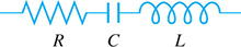
Fig. 12.21
In Chapter 10, we noted that the current and voltage in an ac circuit could be represented by a sine or a cosine curve. Therefore, each reaches peak values periodically. If they reach their respective peak values at the same time, they are in phase. If the voltage reaches its peak before the current, the voltage leads the current. If the voltage reaches its peak after the current, the voltage lags the current (see Example 5 in Section 10.3).
In the study of electricity, it is shown that the voltage across a resistance is in phase with the current. The voltage across a capacitor lags the current by , and the voltage across an inductance leads the current by . This is shown in Fig. 12.22, where, in a given circuit, I represents the current, is the voltage across a resistor, is the voltage across a capacitor, is the voltage across an inductor, and t represents time.
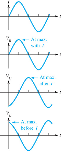
Fig. 12.22
Each element in an ac circuit tends to offer a type of resistance to the flow of current. The effective resistance of any part of the circuit is called the reactance, and it is denoted by X. The voltage across any part of the circuit whose reactance is X is given by where I is the current (in amperes) and V is the voltage (in volts). Therefore,
the voltage across a resistor with resistance R,
the voltage across a capacitor with reactance and
the voltage across an inductor with reactance
are, respectively,
To determine the voltage across a combination of these elements of a circuit, we must account for the reactance, as well as the phase of the voltage across the individual elements. Because the voltage across a resistor is in phase with the current, we represent along the positive real axis as a real number. Because the voltage across an inductance leads the current by , we represent this voltage as a positive, pure imaginary number. In the same way, by representing the voltage across a capacitor as a negative, pure imaginary number, we show that the voltage lags the current by . These representations are meaningful since the positive imaginary axis is from the positive real axis, and the negative imaginary axis is from the positive real axis. See Fig. 12.23.
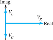
Fig. 12.23
The circuit elements shown in Fig. 12.23 are in series, and all circuits we consider (except Exercises 22 and 23) are series circuits. The total voltage across a series of all three elements is given by which we represent by Therefore,
This expression is also written as
where the symbol Z is called the impedance of the circuit. It is the total effective resistance to the flow of current by a combination of the elements in the circuit, taking into account the phase of the voltage in each element. From its definition, we see that Z is a complex number.
with a magnitude
Also, as a complex number, it makes an angle with the x axis, given by
All these equations are based on phase relations of voltages with respect to the current. Therefore, the angle represents the phase angle between the current and the voltage.
NOTE
[The standard way of expressing is to use a positive angle if the voltage leads the current and use a negative angle if the voltage lags the current.]
Using Eq. (12.22), a calculator will give the correct angle even when since Z would be in the fourth quadrant and have a negative phase angle.
If the voltage leads the current, then as shown in Fig. 12.24(a). If the voltage lags the current, then as shown in Fig. 12.24(b).

Fig. 12.24
In the examples and exercises of this section, the commonly used units and symbols for electrical quantities are used. For a summary of these units and symbols, see Appendix B. For common metric prefixes, see Section 1.4.
EXAMPLE 1 Finding impedance and voltage
In the series circuit shown in Fig. 12.25(a), and A current of 2.00 A is in the circuit. Find the voltage across each element, the impedance, the voltage across the combination, and the phase angle between the current and the voltage.
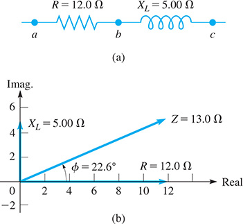
Fig. 12.25
The voltage across the resistor (between points a and b) is the product of the current and the resistance This means The voltage across the inductor (between points b and c) is the product of the current and the reactance, or
To find the voltage across the combination, between points a and c, we must first find the magnitude of the impedance. Note that the voltage is not the arithmetic sum of and as we must account for the phase.
By Eq. (12.20), the impedance is (there is no capacitor)
with magnitude
Thus, the magnitude of the voltage across the combination of the resistor and the inductance is
The phase angle between the voltage and the current is found by Eq. (12.22). This gives
The voltage leads the current by , and this is shown in Fig. 12.25(b).
EXAMPLE 2 Finding impedance and phase angle
For a circuit in which and find the impedance and the phase angle between the current and the voltage.
By the definition of impedance, Eq. (12.20), we have
where the magnitude of the impedance is
The phase angle is found by
The angle is given directly by the calculator, and it is the angle we want. As we noted after Eq. (12.22), we express as a negative angle if the voltage lags the current, as it does in this example. See Fig. 12.26.

Fig. 12.26
From the values above, we write the impedance in polar form as
Note that the resistance is represented in the same way as a vector along the positive x-axis. Actually, resistance is not a vector quantity but is represented in this manner in order to assign an angle as the phase of the current. The important concept in this analysis is that the phase difference between the current and voltage is constant, and therefore any direction may be chosen arbitrarily for one of them. Once this choice is made, other phase angles are measured with respect to this direction. A common choice, as above, is to make the phase angle of the current zero. If an arbitrary angle is chosen, it is necessary to treat the current, voltage, and impedance as complex numbers.
EXAMPLE 3 Finding voltage
In a particular circuit, the current is A and the impedance is The voltage across this part of the circuit is
The magnitude of the voltage is
Because the voltage across a resistor is in phase with the current, this voltage can be represented as having a phase difference of zero with respect to the current. Therefore, the resistance is indicated as an arrow in the positive real direction, denoting the fact that the current and the voltage are in phase. Such a representation is called a phasor. The arrow denoted by R, as in Fig. 12.25(b) and Fig. 12.26, is actually the phasor representing the voltage across the resistor. Remember, the positive real axis is arbitrarily chosen as the direction of the phase of the current.
To show properly that the voltage across an inductance leads the current by , its reactance (effective resistance) is multiplied by j. We know that there is a positive angle between a positive real number and a positive imaginary number. In the same way, by multiplying the capacitive reactance by we show the difference in phase between the voltage and the current in a capacitor, with the current leading. Therefore, represents the phasor for the voltage across an inductor and is the phasor for the voltage across the capacitor. The phasor for the voltage across the combination of the resistance, inductance, and capacitance is Z, where the phase difference between the voltage and the current for the combination is the angle
NOTE
[From this, we see that multiplying a phasor by j means to perform the operation of rotating it through . For this reason, j is also called the j-operator.]
EXAMPLE 4 Multiplication by j
Multiplying a positive real number A by j, we have which is a positive imaginary number. In the complex plane, Aj is from A, which means that by multiplying A by j we rotated A by j . Similarly, we see that which is a negative real number, rotated from Aj. Therefore, successive multiplications of A by j give us
See Fig. 12.27. (See Exercise 36 in Section 12.3.)

Fig. 12.27
An alternating current is produced by a coil of wire rotating through a magnetic field. If the angular velocity of the wire is the capacitive and inductive reactances are given by
Therefore, if C, and L are known, the reactance of the circuit can be found.
EXAMPLE 5 Finding voltage-current phase difference
If and find the impedance and the phase difference between the current and the voltage.
The voltage lags the current (see Fig. 12.28).
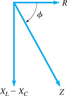
Fig. 12.28
Recall from Section 10.5 that the angular velocity is related to the frequency f by the relation where is in rad/s and f is in Hz. It is very common to use frequency when discussing alternating current.
An important concept in the application of this theory is that of resonance. For resonance, the impedance of any circuit is a minimum, or the total impedance is R. Thus, Also, it can be seen that the current and the voltage are in phase under these conditions. Resonance is required for the tuning of radio and television receivers.
EXAMPLE 6 Resonance
In the antenna circuit of a radio, the inductance is 4.20 mH, and the capacitance is variable. What range of values of capacitance is necessary for the radio to receive the AM band of radio stations, with frequencies from 530 kHz to 1600 kHz?
For proper tuning, the circuit should be in resonance, or This means that
For
and for we have
The capacitance should be capable of varying from 2.36 pF to 21.6 pF.
Exercises 12.7
In Exercises 1 and 2, perform the indicated operations if the given changes are made in the indicated examples of this section.
In Example 1, change the value of to and then solve the given problem.
In Example 5, double the values of L and C and then solve the given problem.
In Exercises 3–6, use the circuit shown in Fig. 12.29. The current in the circuit is 5.75 mA. Determine the indicated quantities.
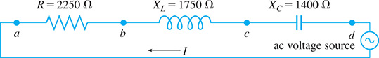
Fig. 12.29
The voltage across the resistor (between points a and b).
The voltage across the inductor (between points b and c).
The magnitude of the impedance across the resistor and the inductor (between points a and c).
The phase angle between the current and the voltage for the combination in (a).
The magnitude of the voltage across the combination in (a).
The magnitude of the impedance across the resistor, inductor, and capacitor (between points a and d).
The phase angle between the current and the voltage for the combination in (a).
The magnitude of the voltage across the combination in (a).
In Exercises 7–10, an ac circuit contains the given combination of circuit elements from among a resistor a capacitor and an inductor If the frequency in the circuit is find (a) the magnitude of the impedance and (b) the phase angle between the current and the voltage.
The circuit has the inductor and the capacitor (an LC circuit).
The circuit has the resistor and the capacitor (an RC circuit).
The circuit has the resistor and the inductor (an RL circuit).
The circuit has the resistor, the inductor, and the capacitor (an RLC circuit).
In Exercises 11–24, solve the given problems.
Given that the current in a given circuit is and the impedance is find the magnitude of the voltage.
Given that the voltage in a given circuit is and the impedance is find the magnitude of the current.
A resistance and a capacitance are in an AM radio circuit. If find the impedance across the resistor and the capacitor.
A resistance and an inductance are in a telephone circuit. If find the impedance across the resistor and inductor.
The reactance of an inductor is for What is the inductance?
A resistor, an inductor, and a capacitor are connected in series across an ac voltage source. A voltmeter measures 12.0 mV, 15.5 mV, and 10.5 mV, respectively, when placed across each element separately. What is the voltage of the source?
An inductance of and a capacitance of 47.0 nF are in series in an amplifier circuit. Find the frequency for resonance.
A capacitance and an inductance are in series in the circuit of a receiver for navigation signals. Find the inductance if the frequency for resonance is 50.0 kHz.
In Example 6, what should be the capacitance in order to receive a 680-kHz radio signal?
A 220-V source with is connected in series to an inductance and a resistance R in an electric-motor circuit. Find R if the current is 0.250 A.
The power P (in W) supplied to a series combination of elements in an ac circuit is where V is the effective voltage, I is the effective current, and is the phase angle between the current and voltage. If across the resistor, capacitor, and inductor combination in Exercise 10, determine the power supplied to these elements.
For two impedances and in parallel, the combined impedance is given by Find the combined impedance (in rectangular form) for the parallel circuit elements in Fig. 12.30 if the current in the circuit has a frequency of 60.0 Hz.

Fig. 12.30
Find the combined impedance (in rectangular form) of the circuit elements in Fig. 12.31. The frequency of the current in the circuit is 60.0 Hz. See Exercise 22.
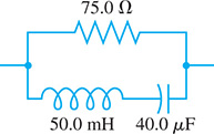
Fig. 12.31
 If the complex number j, in polar form, is multiplied by itself, what is the resulting number in polar and rectangular forms?
In the complex plane, where is the resulting complex number in relation to j?