
Challenge Exercise | Mechanical
In this exercise, you use what you learned about annotation to add annotation to the drawing views.
Note: The following illustration depicts only some of the views that require annotation.
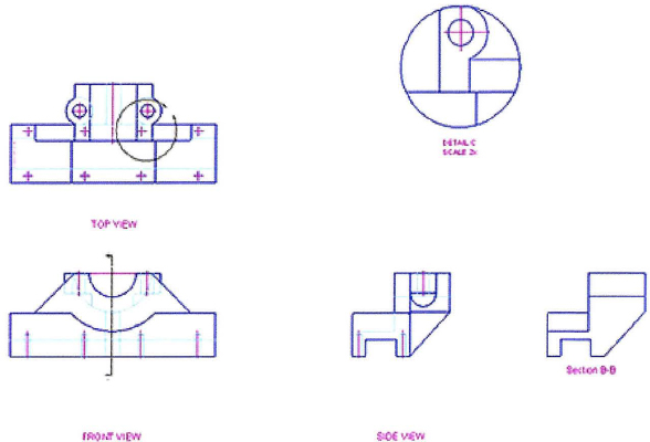
The completed exercise
Completing the Exercise
To complete the exercise, follow the steps in this book or in the onscreen exercise. In the onscreen list of chapters and exercises, click Chapter 7: Annotating the Drawing. Click Challenge Exercise: Mechanical.
![]()
- Open the drawing you saved from the previous challenge exercise, or open M_MECH-Challenge-CHP07.dwg.
- Make initial settings:
- Make the Annotation layer current.
- Thaw the Section Line layer.
- Create a new text style with the following characteristics:
- Style Name: Labels
- Font Name: Arial
- Height: 0
- Width Factor: 0.9000
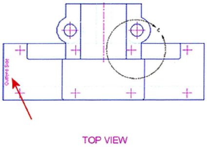
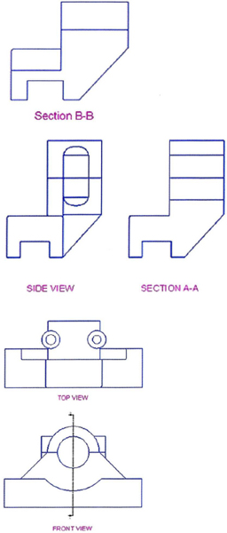
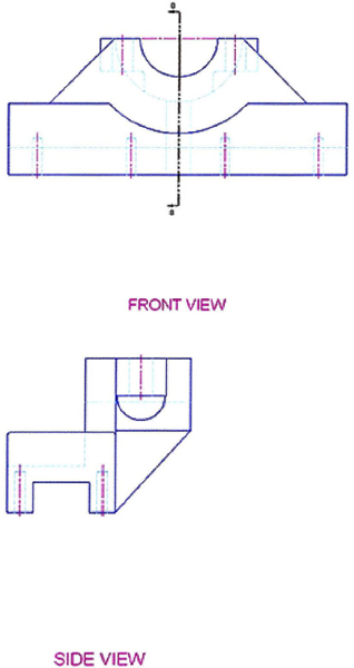
- Annotate the drawing views by adding view labels that are 8.0 mm tall as shown in the following illustrations. Note that the annotation indicated on the left side of the view reads Outfeed Side and needs to be 4.0 mm in height.
- More views
- Save and close all files.
Chapter Summary
Using the annotation commands, you can create and edit the annotation that is typically required in drawings. By using the annotative properties of your annotations, you can create annotations that get reused in many viewports at any desired scale.
Having completed this chapter, you can:
..................Content has been hidden....................
You can't read the all page of ebook, please click here login for view all page.