Lesson 37 | Creating Dimensions
This lesson describes how to use the various dimension commands to place dimensions on your drawings.
Dimensions are a vital element of annotation. They display measurements and illustrate how your drawings meet specifications.
Objectives
After completing this lesson, you will be able to:
- Create different types of dimensions on linear objects.
- Create different types of dimensions on curved objects.
- Enhance dimensions for clarity of purpose.
Creating Dimensions on Linear Objects
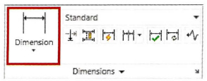
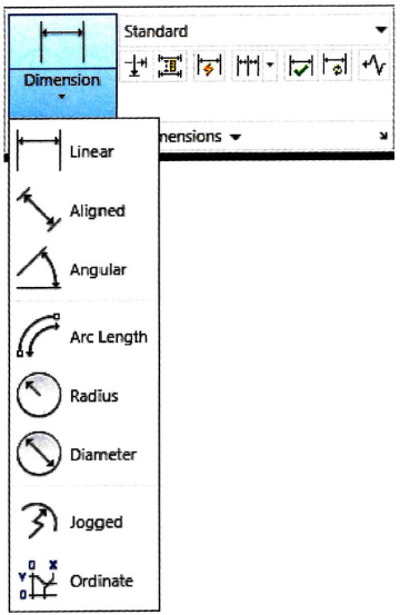
Placing dimensions on objects in the drawing is a straightforward process. Your dimensions will be as accurate as your drawing, provided you use the object snaps correctly. Dimension commands are located on the Annotate tab of the Ribbon. Pay attention to the Command line prompts as they guide you to the required selections.

The following illustration shows a variety of dimensions for linear objects.
Procedure: Creating a Linear Dimension
Use the following command to create horizontal or vertical Linear dimensions:

Command Line: DIMLINEAR, DIMLIN
Ribbon: Annotate tab > Dimensions panel > Linear
The following steps give an overview of creating a Linear dimension:
- Start the Dimlinear command.
- Press ENTER to select the object or, using object snap, select the first extension line origin (1) and the second extension line origin (2).
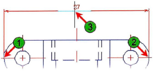
- Click to position the dimension (3).
Practice Exercise | Linear Dimensions
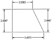
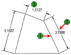
In this practice exercise, you create the object below, and apply linear dimensions as shown.
- To draw your object to dimension:
- Begin with a blank drawing.
- Draw a simple rectangle (any size).
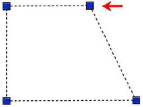
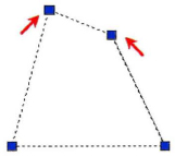
- Use the Grips to stretch one corner of the rectangle.
- Press ESC to deselect the object.
- To create a Linear dimension by selecting two points on the object:
- Begin Linear dimension.
- Using object snap, click to specify the first extension line origin (1).
- Click to specify the second extension line origin (2).
- Click to specify the dimension line location as shown (3).

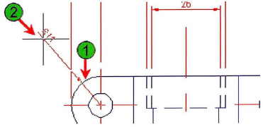
- To create a Linear dimension by selecting the object:
- Begin Linear dimension.
- Press ENTER to select the object.
- Select the object where indicated (1).
- Drag and place the dimension as shown (2).
- Repeat the Linear dimension command.
- Create dimensions (3) and (4).
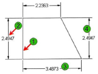
Note: When you dimension the angled line (4), you have the option to create a horizontal or vertical Linear dimension, depending on the direction you drag the dimension.
Procedure: Creating an Aligned Dimension
Use the following command to create a dimension that is aligned to an object or two points:

Command Line: DIMALIGNED
Ribbon: Annotate tab > Dimensions panel > Align
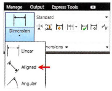
Note: Once you select a dimension type from the list, it becomes the predominant button in the Dimensions panel.
The following steps give an overview of creating an aligned dimension:
- Start the Dimaligned command.
- Press ENTER to select the object or, using object snap, select the first extension line origin (1) and the second extension line origin (2).

- Click to position the dimension (3).
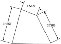
Practice Exercise | Linear Dimensions
In this practice exercise, you create the object below and apply aligned dimensions as shown.
- To draw your object to dimension:
- Begin with a blank drawing.
- Draw a simple rectangle (any size).
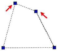
- Use the Grips to stretch the corners of the rectangle.
- Press ESC to deselect the object.
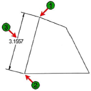
- To create an Aligned dimension by selecting two points on the object:
- Begin the Aligned dimension command.
- Using object snap, click to specify the first extension line origin (1).
- Click to specify the second extension line origin (2).
- Click to specify the dimension line location as shown (3).
- To create an Aligned dimension by selecting the object:
- Begin the Aligned dimension command.
- Press ENTER to select the object.
- Select the object where indicated (l).
- Drag and place the dimension as shown (2).
- Repeat to create dimension (3).
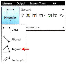
Procedure: Creating an Angular Dimension
Use the following command to create an angular dimension between two lines. The Angular dimension command can also be used to measure the angle between two points on a circle, the angle of an arc, or the angle between three points.

Command Line: DIMANGULAR, DIMANG
Ribbon: Annotate tab > Dimensions panel > Angular
Note: Once you select a dimension type from the list, it becomes the predominant button in the Dimensions panel.
The following steps give an overview of creating an angular dimension:
- Start the Dimangular command.
- Select the first line segment (1).
- Select the second line segment (2).
- Click to position the dimension (3).
Practice Exercise | Angular Dimensions
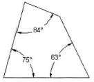
In this practice exercise, you create the object below and apply angular dimensions as shown.
- To draw your object to dimension:
- Begin with a blank drawing.
- Draw a simple rectangle (any size).
- Use the Grips to stretch the corners of the rectangle.
- Press ESC to deselect the object.
- To create an Angular dimension by selecting two lines:
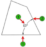
- Begin the Angular dimension command.
- Select the first line (1).
- Select the second line (2).
- Specify the dimension arc line location as shown (3).
Note: You can drag the arc dimension to inside or outside the arc angle.
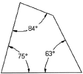
- Repeat to dimension the remaining angles.
Procedure: Creating Baseline Dimensions
Use the following command to create baseline dimensions. Create a Linear, Aligned or Angular dimension first to use the base dimension. By default, the baseline dimension is built off of the last dimensioned line selected.

Command Line: DIMBASELINE, DIMBASE
Ribbon: Annotate tab > Dimensions panel > Baseline

The following steps give an overview of creating baseline dimensions:
- To use the Baseline dimension, begin by creating the base dimension.
Note that by default, the last linear, aligned or angular dimension created is used as the base dimension, or you are prompted to select a base dimension.
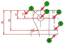
- For the baseline dimension, begin the Linear dimension and select the first extension line origin (1) and the second extension line origin (2).
Note that the baseline will be built off of the first extension line origin.
- Click to position the Linear dimension (3).
- Start the Dimbaseline command. Select the next extension line (4).
- Continue selecting points (5 and 6) for as many baseline dimensions as you require.
- Press ENTER to end the Baseline command.
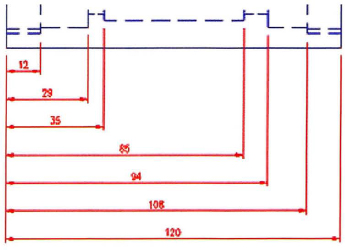
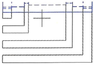
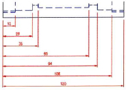
Practice Exercise | Baseline Dimensions
In this practice exercise, you create the object below and apply baseline dimensions as shown.
- To create your base dimension using the Linear dimension command:
- Begin Linear dimension.
- Specify the first extension line (1).
- Specify the second extension line (2).
- Specify the dimension location.
Note: Baseline dimensions build off of the first extension line origin.
- To add the Baseline dimensions:
- Continue with the Baseline command.
- Specify a second extension line at (1), (2) and (3).
- Press ENTER twice to complete the command.
Note: If you choose to select a base dimension that was already created, be sure to select it towards the extension line that you want to be the baseline. In this example, it would be the left side of the Linear dimension you created.
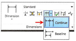
Procedure: Creating Continuous Dimensions
Use the following command to continue placing dimensions based on a Linear, Aligned or Angular dimension. Select or create the base dimension. The continued dimensions are built from the last dimension origin point.

Command Line: DIMCONTINUE, DIMCONT
Ribbon: Annotate tab > Dimensions panel > Continuous
The following steps give an overview of creating continuous dimensions:
- To use the Continue dimension, begin by creating the base dimension.
Note that by default, the last linear, aligned or angular dimension created is used as the base dimension, or you are prompted to select a base dimension.
- For the base dimension, begin the Linear dimension. Use object snaps to select the first extension line origin (1) and the second extension line origin (2).
Note that the continuous dimensions will be built off of the second extension line origin.
- Click to position the Linear dimension (3).
- Start the Dimcontinuous command. Select the next extension line (4).
- Using object snap, continue selecting points (5 and 6) or objects for as many continuous dimensions as you require.
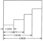
Practice Exercise | Continuous Dimensions
In this practice exercise, you create the object below and apply continuous dimensions as shown.
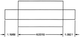
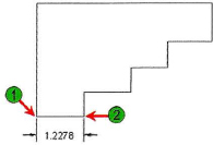
- To create your base dimension using the Linear dimension command:
- Begin Linear dimension.
- Specify the first extension line (1).
- Specify the second extension line (2).
- Specify the dimension location.
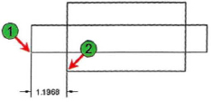
Note: Continuous dimensions build off of the second extension line origin.
Note: When you choose the dimension origin points as indicated, the gap between the dimension extension lines and the object is visible.
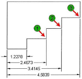
- To add the Continuous dimensions:
- Begin the Continuous dimension command.
- Specify a second extension line at (1) and (2).
- Press ENTER twice to complete the command.
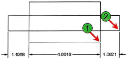
Note: If you choose to select a base dimension that was already created, be sure to select it towards the extension line you want the Continuous dimension to follow. In this example, it would be the side of the Linear dimension you created.
Dimensions for Linear Objects Guidelines
- Always use Object Snaps to select the dimension origin points.
- Depending on the geometry you are dimensioning you may select objects to dimension rather than specifying the endpoints.
- A Linear dimension will be horizontal or vertical depending on the direction you drag the dimension line from the object.
- An Angular dimension may be located inside or outside the angle depending on where you drag the arc line location.
- To ensure that Continuous and Baseline dimensions build correctly, create the base Linear, Aligned, or Angular dimension choosing the first and second origin points accordingly. Baseline dimensions are built from the first origin point. Continuous dimensions are built from the second origin point.
- When you select the base dimension for your Continuous or Baseline dimensions, select the dimension towards the side that you want the continued or baseline dimension to reference.
- Adjust the location of the dimension using Grips when necessary.
- If the origin point you selected is incorrect, zoom in closer to the object and use the grips to relocate the origin point to the object.
Tip
The Dimlinear and Dimaligned commands prompt you for two points or to select an object. Press ENTER to select the object to dimension. This is often quicker than selecting two points.

Creating Dimensions on Curved Objects
Using commands to place dimensions on curved objects in the drawing is a straightforward process. Pay attention to the command prompts as they guide you through the required selections. These dimensions can be selected from the list on the Dimensions panel.
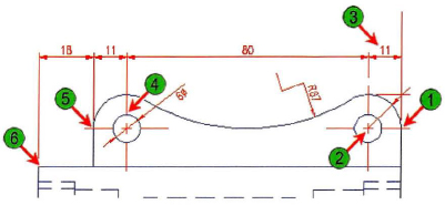
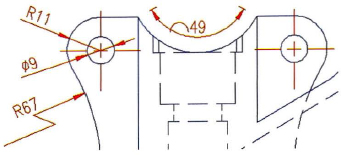
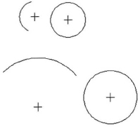
The following illustration shows a variety of dimensions for curved objects.
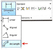
Procedure: Creating an Arc Length Dimension
Use the following command to dimension the length of an arc.

Command Line: DIMARC
Ribbon: Annotate tab > Dimensions panel > Arc Length
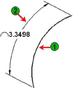
The following steps give an overview of creating an arc length dimension:
- Start the Dimarc dimension command.
- Select an arc (1).
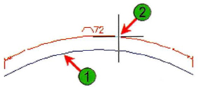
- Click to position the arc length dimension (2).
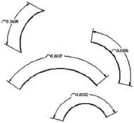
Practice Exercise | Arc Length Dimensions
In this practice exercise, you draw several arcs, then use the Arc Length command to dimension the arcs.
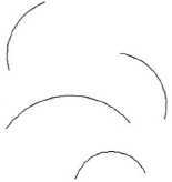
- To create Arc Length dimensions on the arcs you have drawn:
- Begin the Arc Length command.
- Select the arc (1).
- Specify the arc length dimension location (2).
- Repeat the Arc Length command to dimension the remaining arcs.
Note: The arc length symbol can precede the dimension text, be above the dimension text, or be turned off. This symbol can be controlled using the DIMSTYLE command. Select: Modify > Symbols and Arrows > Arc Length Symbol.
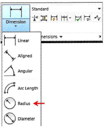
Procedure: Creating a Radius Dimension
Use the following command to dimension the radius of a circle or arc.

Command Line: DIMRADIUS, DIMRAD, DRA
Ribbon: Annotate tab > Dimensions panel > Radius
The following steps give an overview of creating a radius dimension:
- Start the Dimradius command.
- Select an arc or circle (1).
- Click to position the dimension (2).
Practice Exercise | Radius Dimensions
In this practice exercise you use the Radius Dimension command; first, create a drawing that resembles the object shown below.
Note: To ensure a manageably sized drawing, begin with a blank drawing based on the acad.dwg template.
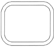
- To create the object to dimension:
- Draw a rectangle.
- Begin the Fillet command and set the fillet radius to .25 or .5.
- Use the Polyline option of the Fillet command to fillet all 4 corners of the rectangle.
Note: A rectangle is a polyline meaning all the lines are connected and recognized as a single object.
- Begin the Offset command.
- Specify an offset distance of .15.
- Offset the polyline.
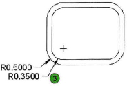
- To dimension the outside fillet:
- Begin the Radius command.
- Select the arc (1).
- Specify the dimension line location (2).
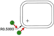
- Repeat the command to dimension the inside radius (3).
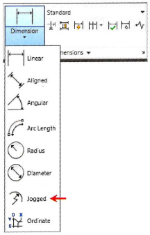
Procedure: Creating a Jogged Radius Dimension
Use the following command to dimension a radius where you want to override the center origin point of the dimension to another location. This will create a jogged radial dimension.

Command Line: DIMJOGGED
Ribbon: Annotate tab > Dimensions panel > Jogged
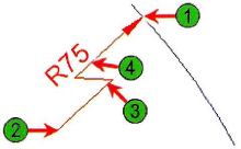
The following steps give an overview of creating a jogged radius dimension:
- Start the Dimjogged command.
- Select an arc or circle (1).
- Specify a center location override (2).
- Specify a dimension line location (3).
- Specify the jog location (4).
Practice Exercise | Jogged Radius Dimensions
In this practice exercise you draw an arc and use the Jogged radius dimension command.
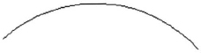
- Draw an arc.
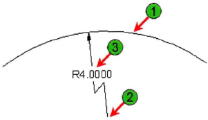
- To create a jogged radius:
- Enter DIMJOGGED and press ENTER.
- Select the arc (1).
- Specify the center point location override (2).
- Specify the dimension line location (3).
- Specify the jog location.
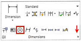
Procedure: Creating a Diameter Dimension
Use the following command to dimension the diameter of a circle or arc:.

Command Line: DIMDIAMETER, DIMDIA
Ribbon: Annotate tab > Dimensions panel > Baseline
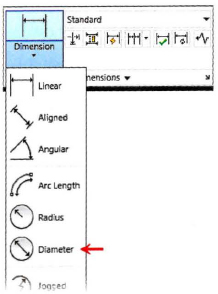
The following steps give an overview of creating a diameter dimension:
- Start the Dimdiameter command.
- Select an arc or circle (1).
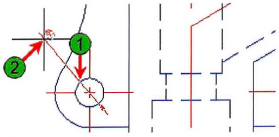
- Click to position the dimension (2).
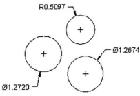
Practice Exercise | Diameter Dimensions
In this practice exercise you draw several circles and use the Diameter dimension command.
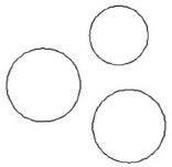
- To dimension the diameter of a circle:
- Begin the Diameter dimension command.
- Select the circle (1).
- Specify the dimension line location (2).
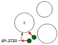
- Repeat the Diameter command to dimension the remaining circles.
Procedure: Creating Center Marks
Use the following command to create a center mark.

Command Line: DIMCENTER
Ribbon: Annotate tab > extended Dimensions panel > Center Mark
Note: You can type DIMCEN to change the value (size) of the Center Marks.
The following steps give an overview of creating center marks:
- Start the DIMCENTER command.
- Select an arc or circle (1).
Note: The Center Mark size and appearance is set in the Dimension Style or you can change the size by typing DIMCEN.
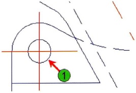
Practice Exercise | Create Center Marks
In this practice exercise you draw several circles and arcs and place a Center Mark in each one.
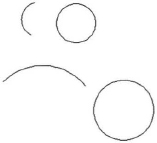
- Draw several circles and arcs.
- To place center marks in the circles and arcs:
- Begin the Center Mark dimension command.
- Select a circle or arc.
- Repeat and continue to place a center mark within each object.
Note: The Center Mark appearance and size is controlled using the DIMSTYLE command (select: Modify > Symbols and Arrows > Center marks).
Enhancing Dimensions
Placing dimensions on objects in the drawing is a straightforward process, however you may need to use some additional tools to produce drawings to your desired standard. Pay attention to the command prompts; they guide you through the required selections.
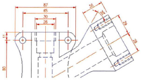
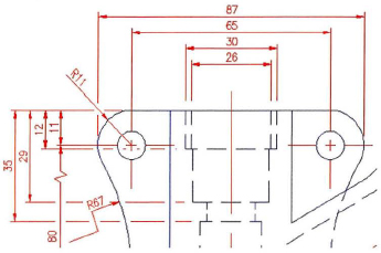
The following illustration shows a variety of dimensions that have been enhanced for adherence to a drafting standard.
Procedure: Placing a String of Quick Dimensions
Use the following command for placement of a semi-automated string of quick dimensions:

Command Line: QDIM
Ribbon: Annotate tab > Dimensions panel > Quick Dimension
The following steps give an overview of the Quick Dimension command. This command only works for model space dimensioning.
- Start the Qdim command.
- Select the geometry to dimension using standard selection methods.
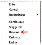
- By default, a series of continuous dimensions is previewed. Right-click anywhere in the drawing to change the dimension types or options. Available options are: Continuous, Staggered, Baseline, Ordinate, Radius, Diameter, Datumpoint, Edit, and Settings.
- Click to position the dimensions.
The dimensions are created.
Warning
QDIM is not available in AutoCAD LT®.

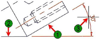
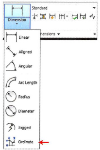
Procedure: Ordinate Dimensions
Use the following command to create Ordinate dimensions.

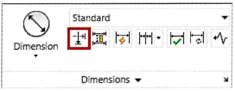
Command Line: DIMORDINATE, DIMORD
Ribbon: Annotate tab > Dimensions panel > Ordinate
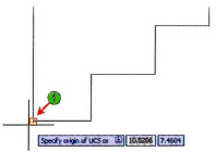
The following steps give an overview of creating Ordinate Dimensions. To dimension using Ordinate Dimensions, you must first change the Origin point.
- Enter UCS and press ENTER. Specify the origin point on the object for the Ordinate dimensions to reference. Accept your selection by pressing ENTER.
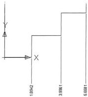
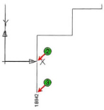
- Start the Dimordinate command.
- Use object snap to specify the feature location (2), then specify the leader endpoint (3).
- Repeat Dimordinate and continue to select the next feature location and leader endpoint. Then return the UCS origin back to World.
Note you can use the Ordinate option with the Quick Dimension command.
Procedure: Breaking Dimensions
Use the following command to break dimension or extension lines where they overlap other lines:

Command Line: DIMBREAK
Ribbon: Annotate tab > Dimensions panel > Break
The following steps give an overview for breaking dimensions:
- Start the Dimbreak command.
- Select the dimension to break (1).
Note: Use the Multiple option to break multiple dimensions.
- Select objects to break the dimension (2) and press ENTER.
Note: Simply press ENTER to break the dimension automatically wherever it intersects with other objects or dimensions.
Procedure: Creating Jogged Linear Dimensions
Use the following to command to add a jog line to a dimension line.
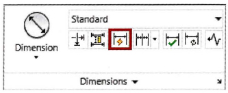
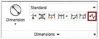
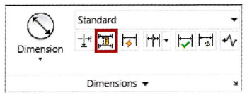
Command Line: DIMJOGLINE
Ribbon: Annotate tab > Dimensions panel > Jog Line
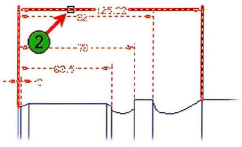
The following steps give an overview for adding a Jog Line to a dimension:
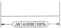
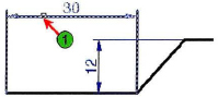
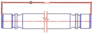
- Create a linear dimension between two points and enter the text override value to represent the stated value
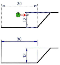
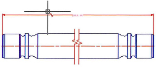
- Start the Dimjogline command and select a linear dimension.
- Click a point on the dimension to place the jog line symbol.
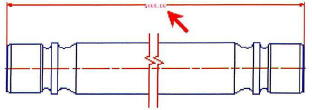
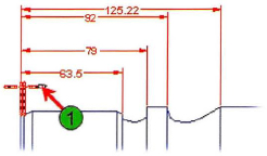
Removing a Linear Jog from a Dimension
To remove the jog symbol from a jogged linear dimension, use the Remove option of the Dimjogline command.
![]()
Procedure: Spacing Dimensions
Use the following command to adjust the space between parallel linear dimensions.

Command Line: DIMSPACE
Ribbon: Annotate tab > Dimensions panel > Adjust Space
The following steps give an overview for spacing dimensions uniformly after they have been placed in the drawing:
- Start the Dimspace command and select the base dimension.
- Select the dimensions to be spaced from the base dimension, and press ENTER.
- Enter a value for spacing the dimensions, or press ENTER to use the automatic method.
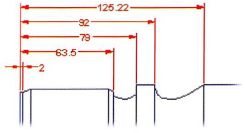
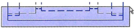
Dimensions Are Associative
When you create dimensions, they are associative to the geometry or points you select. If the geometry changes size, the dimension updates accordingly.
![]()
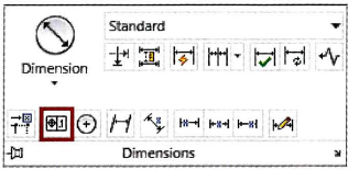
Procedure: Adding Tolerances
Use the following command to add a dimension Tolerance to your drawing:

Command Line: TOLERANCE, TOL
Ribbon: Annotate tab > Dimensions panel > Tolerance
The following steps give an overview of adding a dimension Tolerance:
- Start the Tolerance command.
- From the Geometric Tolerance dialog box, select the desired Symbol, Tolerance and Datum. Click OK.
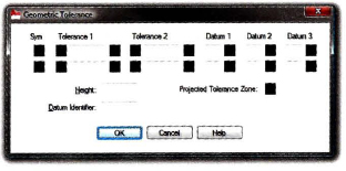
- Click to place the Tolerance in the drawing.

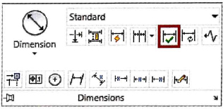
Procedure: Inspecting Dimensions
Use the following command to add an inspection label to a selected dimension:

Command Line: DIMINSPECT
Ribbon: Annotate tab > Dimensions panel > Inspect
The following steps give an overview of creating an inspection label.
- Start the Diminspect command.
- From the Inspection Dimension dialog box, select a Shape and a Label and/or Inspection rate.
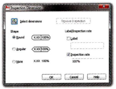
- Select the dimension(s) and click OK.