Lesson 10 | Selecting Objects in the Drawing
This lesson describes how to select objects using several different options and methods.
You need to select objects in your drawing in order to modify and manipulate those objects. As your drawing grows in complexity and contains more objects, you need to use different selection methods to select these objects efficiently.
Objectives
After completing this lesson, you will be able to:
- Use implied, manual window, and crossing selection methods to select objects.
- Select objects for grip editing and identify the type of editing that can be done using grips.
- Use several different selection methods to select objects.
Using a Window to Select Objects
An object or group of objects that you select is also called a selection set. There are a variety of methods for selecting, adding, and removing objects within this selection set.
Selection sets are useful when you want to modify a number of objects. You can create a selection set either before or after activating the pertinent command.
If you want to select an individual object, you simply click it. You can continue to select additional objects as needed. As each new object is added to the selection set, the object's appearance changes to dashed lines.
In response to the Select Objects prompt, there are many methods you can use to select several objects at the same time.
Implied Window Selection
An implied window is a method of selecting objects by creating a selection window around those objects. To select objects using an implied window, click in a blank area of the drawing then drag the cursor from left to right and click the opposite corner of the selection window. Objects enclosed completely within the implied window will be selected.
- Only objects that are entirely within the rectangular window are selected.
- If any part of an object is outside the window, that object is not selected.
- Although the drag movement must be from left to right, it can also be up and across, or down and across the drawing area. The drag movement shown here is up and across.
- The window selection area has a solid outline and a differently colored shading to distinguish it from that used in a crossing selection.
- The shaded area indicates the points in space used to define the corners of the rectangular Window.
Manual Window Selection
You can define a selection window by using the Window selection method. In response to any Select Objects prompt, enter W and press ENTER. This enables you to create a regular selection window in which you are not restricted as to the direction of the cursor movement when defining the points. When you specify the Window option, you can define the window from left-to-right or right-to-left, and it always results in a regular selection window. Only objects that are completely within the selection window will be included in the selection set.
Implied Crossing Selection
Implied crossing means that you have not manually specified a specific selection method. To make a crossing selection, you specify opposite corners that define a rectangular area. The first corner point must be in your drawing area, but cannot be touching any existing objects. After specifying the first corner point, you drag the cursor from right to left to create a crossing selection that is in the opposite direction of the previous Window selection.
- All objects that are within or touched by the rectangular crossing window are included in the selection set.
- Although the drag movement must be from right to left, it can be up and across or down and across the drawing area.
- The crossing window has a dashed outline and a differently colored shading to distinguish it from that used in a window selection.
- The shaded area indicates the points in space that were used to define the corners of the rectangular window.
Manual Crossing Selection
You can define a non-implied Crossing Window by using the Crossing Window selection method. In response to any Select Objects prompt, enter C and press ENTER. This enables you to create a Crossing selection window where the direction of the cursor movement is not restricted when you define the points. When you specify Crossing Window, you can define the window from left to right or right to left, and it always results in a Crossing selection window.
Guidelines
- Implied windowing enables you to automatically create a selection window by clicking two points in a blank part of the drawing area to define the selection window.
- You can create an implied window when the command line is blank (no command is active), or in response to a Select objects prompt.
- Noun-Verb selection is on by default in the software options. This enables you to select objects before starting a command to modify those objects.
Object Selection with Grips
Grips are selectable points on geometry that you use to initiate editing of the selected object. Grips appear when you select an object and no command is currently active.
Grips Defined
Grips on selected objects are displayed as colored boxes. If you click a grip, it changes color and becomes a selected, or hot grip. If you place your mouse over an unselected grip, the color also changes and it becomes a hover grip.
With a hot grip, you can perform editing tasks on the object such as move, mirror, rotate, scale, and stretch. A hover grip can display specific dimension information.
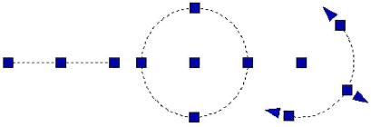
The following illustration shows a common object with grips displayed.
| Unselected grip. This grip is blue by default. Selected grip. | |
| This grip is red by default. | |
| Hover grip. This grip is pink by default. |
Using Hover Grips
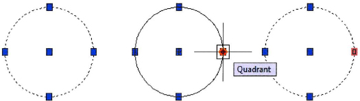
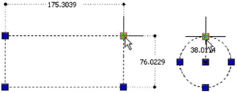
Place your mouse over a grip without selecting it and the grip becomes a hover grip. These grips are used with Dynamic Input to provide real-time dimensional information such as the current length, angle, and diameter of objects in the drawing. The following illustration on the left demonstrates a hover grip on a rectangle. On the right, a hover grip is shown on a circle object.
Using Selected Grips
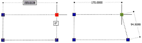
With Dynamic Input turned on, you can select a grip to display fields where you can input new values such as length and radius. On the left, the illustration shows a selected grip where you can change the length of the top line of the rectangle. On the right, the illustration shows the result of changing that value.
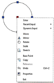
Display Grip Editing Options
Right-click a selected grip to display a menu of grip editing options. The default grip editing option is Stretch. With grip editing, you can perform all of the operations on the menu without having to start a command.
Removing Selection from Grips
To remove a hot grip, press ESC. Press ESC again to remove selection from all grips in the current selection set. To remove a single object from a selection set, press SHIFT + click the object.

Guidelines for Grip Editing
- Grips appear on selected objects only when the command line is blank.
- You can select objects first, so that they are highlighted with grips, then you can choose one of the modify commands for that selection.
- When used in conjunction with Dynamic Input, you can use grips to resize geometry by entering new values for length, angle, radius, and coordinates in the Dynamic Input fields.
- You can combine the grip copy option with your grip editing tasks. Right-click anywhere in the drawing and select Copy. The original object remains unchanged. Multiple copies can be made using the grip editing command options.
- When using the grip copy option, you can make multiple copies at regular intervals based on your first copy by holding down SHIFT when placing your next copy.
- You can perform clipboard edit options of the object selected by right-clicking and choosing: Cut, Copy, Copy with base point or Paste.
- You can change the base point of the object being edited with grips. Right-click anywhere in the drawing and click Base Point to define a new base point for the objects selected.
- You can use the Reference option when rotating or scaling objects during a grip edit. Right-click anywhere in the drawing and click Reference.
Select Objects Options
You can use several keyboard options to select objects on the Select Objects command prompt. These options include Window Polygon, Crossing Polygon, Fence, All, Last, and Previous. Enter the capitalized letter for the option and press ENTER.
The select object options are not so apparent. It is best to memorize those that are most useful. However, if you should enter an incorrect letter at the select object prompt, such as the letter y (which is not an option), AutoCAD® will display the entire list of options as shown in the example below.

Selecting with a Window Polygon
To select objects within a non-rectangular window, use the following procedure:
- At the Select Objects prompt, enter wp (for Window Polygon).
- Specify points that define an area that entirely encloses the objects that you want in the selection set.
- Press ENTER to close the polygon selection area and complete the selection.