Lesson 22 | Using Linetypes
This lesson describes how to use linetypes in your drawings. After completing this lesson, you will be able to describe linetypes and how they are used in a drawing and use the Linetype Manager to add linetypes to your drawing.
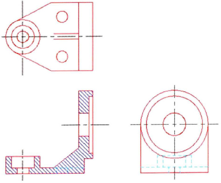
Linetypes are used to distinguish objects in the drawing from one another. You can use them to represent hidden geometry in a specific view, to show centerlines for dimensioning, or perhaps just to add clarity to the drawing.
For example, the following illustration shows a solid linetype used for geometry and a centerline linetype used for centerlines for dimensioning. The dashed linetype indicates hidden geometry.
Objectives
After completing this lesson, you will be able to:
- Describe linetypes and how they are used in a drawing.
- Use the Linetype Manager to add linetypes to your drawing.
About Linetypes
In a typical drawing, you find linetypes associated with many objects. While the specific linetypes used may vary from one discipline to another, the concept of using linetypes remains consistent. They are always used to distinguish objects from one another and to make the drawing easier to read and understand.
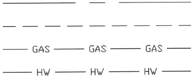
The following illustration contains continuous, hidden, and center linetypes. Each of these linetypes have meaning within the discipline in which they are used.

Linetypes Defined
Linetypes are an attribute of an object that determines how it looks. The linetype helps to distinguish one object from another in a design. For example, a hot water line could be represented by the HW linetype and a gas line in a building could be represented by the GAS linetype.
This image shows common linetypes used in drafting and design.
Linetype Examples
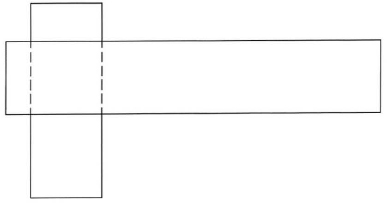
In the following image, you see two pieces of steel overlapping one another. It is impossible to tell which object lies on top of the other.
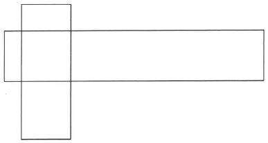
This second image uses hidden lines on the vertical steel object to show you that it lies beneath the horizontal piece of steel.
Linetype Key Points
- Linetypes are used to distinguish objects from one another.
- Linetypes add visual clarity to the drawing.
Adding Linetypes to Your Drawing
To add linetypes to your drawing, you generally assign the linetype to layers and then create objects on the appropriate layers. The object's linetype can be set to ByLayer, which means the object assumes the linetype of the layer.
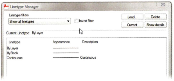
By default, the only linetype available in the drawing is Continuous. To use additional linetypes, you must load them into the drawing. The primary method for adding linetypes to the drawing is with the Linetype Manager.
Command Access
About the Linetype Manager
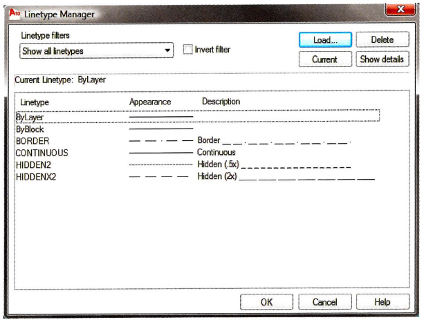
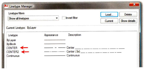
The Linetype Manager dialog box displays all of the linetypes that are currently loaded in the drawing. To load additional linetypes, click Load. To delete linetypes, select the linetype and click Delete. You cannot delete a linetype if it is currently being referenced by other objects in the drawing.
Loading Linetypes
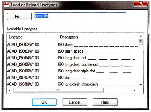
When you select Load from the Linetype Manager dialog box a list of linetypes provided by AutoCAD appears that lets you add additional linetypes to the drawing. You can scroll through the list and select the desired linetypes.
Loading Linetypes from the Layer Property Manager
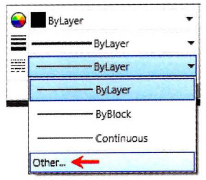
You can also add linetypes to a drawing from the Layer Properties Manager. Click to assign the linetype to a layer. If the linetype is not available in the Select Linetype dialog box, click Load to load the linetype using the Load or Reload Linetypes dialog box.
![]()
Controlling Linetype Scale
Depending on the size of the objects in your drawing, you may have to adjust the linetype scale in order for the lines to appear correctly. For example, to see the gaps in a centerline that is 12 units long, you would set your linetype scale to 1.0, but to see the gaps correctly in a centerline that is 240 units long, you would set your linetype scale to 10.0.
In the following illustration, both lines are center linetypes, but the lower line appears with a more dense pattern as a result of a smaller linetype scale.
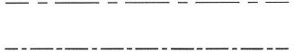
You can control linetype scale in the drawing using two different methods.
- LTSCALE: This is a global linetype scale factor that affects all of the objects that use linetypes in the drawing. To change the global linetype scale, on the command line, enter LTSCALE and then enter a positive number. The default scale factor is set to 1.
- Linetype Scale property: You can set the linetype scale factor for selected objects. Double-click the object to access the Properties palette (or right-click and select Properties from the shortcut menu). Enter a new value in the Linetype Scale property field. The Linetype Scale property works in combination with the global linetype scale factor for the drawing. For example, if the global linetype scale factor is set to 2 and the linetype scale property is set to 0.5, the net result is a linetype scale factor of 1 for the selected object.
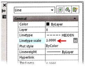
Properties Palette
Procedure: Adding Linetypes to a Drawings
The following steps give an overview of adding linetypes to a drawing.
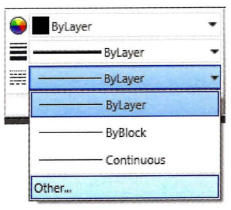
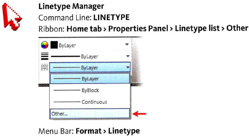
- On the ribbon, click Home tab > Properties panel > Linetype list > Other.
- In the Linetype Manager, click Load.
- In the Load or Reload Linetypes dialog box, select the linetypes. Click OK.
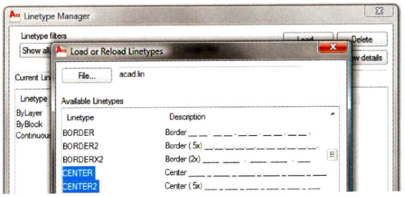
Press SHIFT or CTRL to select more than one linetype.
- The selected linetypes appear in the Linetype Manager. Click OK.
- The linetypes are now available to apply to layers or individual objects.
Linetype Management Guidelines
- By default, a blank drawing will contain only one linetype, the continuous linetype.
- Add only the linetypes that you need for your drawing.
- Delete linetypes that are not being referenced or used from the Linetype Manager dialog box or with the PURGE command.
- A linetype that is being referenced or used cannot be deleted.
- To use other linetypes, you must load them into the drawing first and then apply them to the object or layer.
- Control linetype scale with the LTSCALE command. For example, an LT scale of 24 will multiply the size of all of the linetypes in a drawing by 24.
- Set the linetype scale of individual objects only when necessary using the Properties palette. Linetype scale settings made to individual objects are multiplied by the overall LTSCALE factor.
- Certain linetypes are available at 2 times the normal size. Example: HIDDEN, HIDDEN2 (.5x) and HIDDENX2 (2x).
- By default, all object properties are drawn in the ByLayer mode, so objects will take on the property settings of the current layer. You can override the default mode by selecting a specific linetype from the Linetype list on the Properties panel.