
Exercise | Create and Modify Polylines
In this exercise, you create a polyline that includes lines and arcs of varying widths. You also change the width for all segments of a polyline and then fillet the polyline and list its properties.
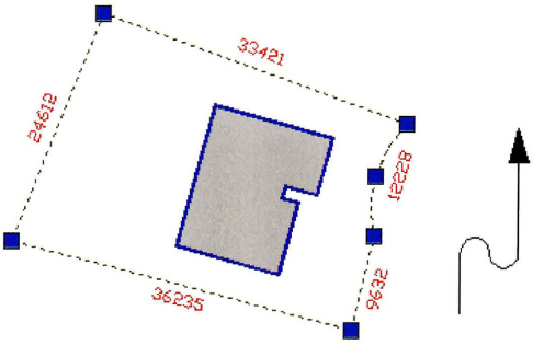
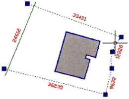
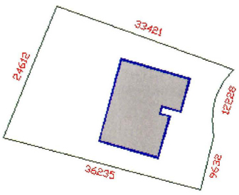
The completed exercise
Completing the Exercise
To complete the exercise, follow the steps in this book or in the onscreen exercise. In the onscreen list of chapters and exercises, click Chapter 11: Creating Additional Drawing Objects. Click Exercise: Create and Modify Polylines.
![]()
- Open M_Polylines.dwg.
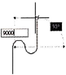
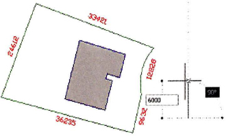
- In the next few steps, you create a custom arrow:
- On the Home tab, click Modify panel > Polyline.
- To set the start position, click anywhere to the right of the existing geometry.
- Move the cursor straight up.
- Enter 6000. Press ENTER.
- To create polyline arc segments:
- Right-dick. Click Arc.
- Move the cursor directly to the right.
- Enter 3000. Press ENTER.
- Move the cursor farther to the right.
- Enter 3000. Press ENTER.

- To switch back to polyline line segments:
- Right-click. Click Line.
- Move the cursor straight up.
- Enter 9000. Press ENTER.
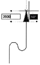
- To add width for the arrowhead:
- Right-click. Click Width.
- For starting width, enter 2000. Press ENTER.
- For ending width, enter 0. Press ENTER.
- To finish the polyline:
- Move the cursor straight up.
- Enter 3500. Press ENTER.
- Press ENTER to complete the object.
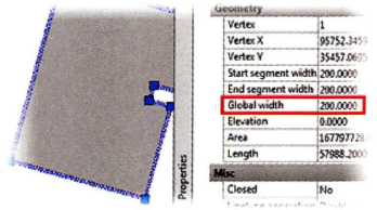
- To edit the polyline:
- Select and right-click the blue outline of the structure.
- On the shortcut menu, click Properties.
- On the Properties palette, for the Global Width, enter 200.
- Press ESC to clear the selection.
- Click the arc in the dark green lot boundary. The grips are displayed, showing the arc as part of a polyline. Notice that the far left green line is not part of the polyline.
- Press ESC.
- To add a line to the polyline using the Fillet command:
- On the Home tab, click Modify panel > Fillet.
- Click the bottom polyline (1) as shown.
- Press SHIFT and click the far left line (2) as shown.
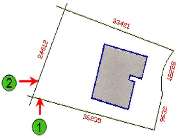
- Click the far left line.
Notice that it is now part of the original polyline.
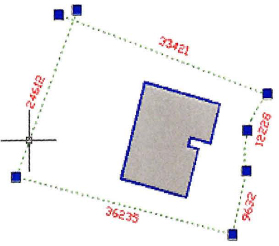
- Grip edit the top left ends of the polyline to form a corner as shown.
- To determine the area and perimeter of the new polyline:
- On the command line, enter list to start the List command.
- Click the top green line.
- Press ENTER.
- In the AutoCAD® Text Window, take note of the area and perimeter values for this closed polyline.
- Close all files. Do not save.
..................Content has been hidden....................
You can't read the all page of ebook, please click here login for view all page.