
Exercise | Create a Chamfered Corner
In this exercise, you create chamfer features using the Multiple, Distance, and Angle options of the Chamfer command. When you have completed the exercise, you will be able to use the Chamfer command to add chamfer features to geometry in other drawings.
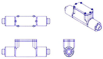
The completed exercise
Completing the Exercise
To complete the exercise, follow the steps in this book or in the onscreen exercise. In the onscreen list of chapters and exercises, click Chapter 5: Altering Objects. Click Exercise: Create a Chamfered Corner.
![]()
- Open M_Create-Chamfers.dwg.
- Zoom in on the lower left view of the drawing.
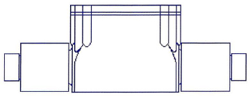
- To create a 1-unit chamfer:
- Start the Chamfer command.
- Right-click anywhere in the drawing window. Click Distance.
- When prompted for the first chamfer distance, enter 1. Press ENTER.
- Press ENTER for the second chamfer distance, as it defaults to the value of the first chamfer distance.
- Right-click anywhere in the drawing window.
- Click Multiple. This enables you to create multiple chamfers without restarting the Chamfer command.
- To complete the chamfer:
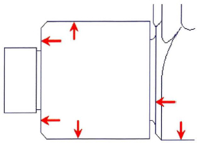
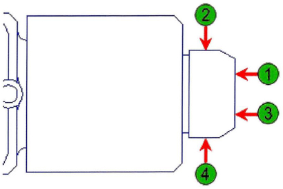
- Select the lines indicated in the following image near their intersections.
Note: The chamfers have already been applied in this image. You may need to turn on the Trim option if it is off.
- DO NOT exit the chamfer command. Proceed to the next step.
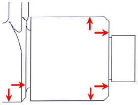
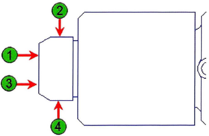
- Select the lines indicated in the following image near their intersections.
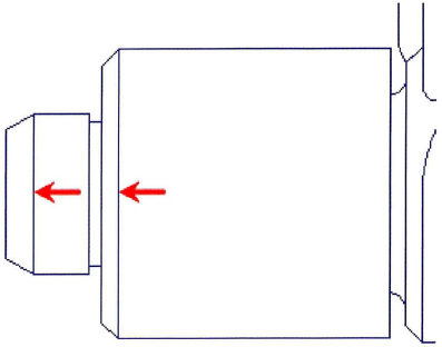
- Select the lines near their intersections as shown in the following image. Press ENTER to end the Chamfer command.
- Use Zoom and Pan to display the top-left view in the drawing.

- To create more 1-unit chamfers in this view:
- Repeat the chamfers on the right side of the view. Press ENTER to end the Chamfer command.
- To create additional chamfers using the Angle and Multiple options:
- Press ENTER to repeat the Chamfer command.
- Right-click anywhere in the drawing window.
- Click Angle.
- Enter 1 for the chamfer length on the first line.
- Enter 60 for the chamfer angle from the first line.
- Right-click anywhere in the drawing window.
- Click Multiple.
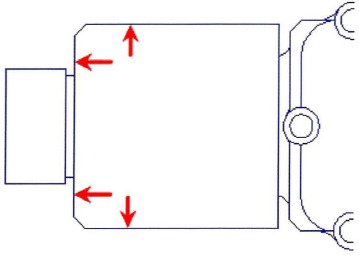
- Select the edges in the order indicated in the following image.
Note: The chamfers have already been applied in this image.
- Select the edges on the opposite side of the view.
- Use Zoom and Pan to display the lower-left view as shown.
- Apply the chamfers to the edges of the part on both sides of the view.
- Press ENTER to end the Chamfer command.

- Using the Line command, draw line segments at each location in which a chamfer was created.
- Zoom to display your entire drawing.
- Close all files without saving.
..................Content has been hidden....................
You can't read the all page of ebook, please click here login for view all page.