Exercise | Modify a Dimension Style
In this exercise, you modify the existing dimension style to allow the dimensions to appear correctly on the sheet. You also change the dimension style to display architectural ticks instead of arrows, and alternate units.
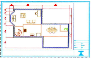
The completed exercise
Completing the Exercise
To complete the exercise, follow the steps in this book or in the onscreen exercise. In the onscreen list of chapters and exercises, click Chapter 8: Dimensioning. Click Exercise: Modify a Dimension Style.
![]()
- Open M_Dimension-Styles.dwg.
Note: The red lines around the floor plan indicate objects that are actually dimensions, but the annotative scale is not currently set for the dimension text or other features to be visible.
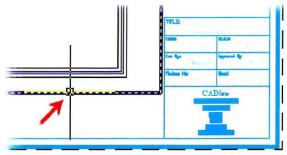
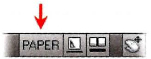
- Click the Paper button on the status bar to change the display to Model space.
- To modify the current dimension style's arrowhead:
- Select the Annotate tab on the ribbon. On the Dimensions panel, click Dimension Style. The current dimension style is ISO-25.
- In the Dimension Style Manager, click Modify.
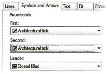
- In the Modify Dimension Style dialog box, Symbols and Arrows tab, under Arrowheads, select Architectural Tick from the First list.
Note: the Second arrowhead will automatically default to the same selection.
- To modify the current dimension style's text style setting:
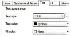
- Click the Text tab.
- In the Text style list, select TECH.
Note: The text height for the dimensions is set to 2.5.
- To modify the dimension style to be annotative:
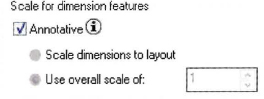
- Click the Fit tab.
- Under Scale for Dimension Features, click Annotative.
- Click OK.
- In the Dimension Style Manager, click Close. Note that no changes in the drawing are visible.
- To set the model space annotation scale:
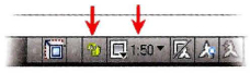
- On the status bar, Annotation Scale list, click 1:50.
- To update the dimensions with the new annotation scale:
- On the Dimensions panel, click Dimension
- Update.
- Enter ALL.
- Press ENTER to complete the selection.
- Press ENTER.
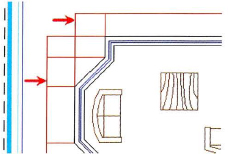
Notice the effect that changing the annotation scale has on the dimensions in the drawing.
- To change the dimension style to display alternate units:
- On the Dimensions panel, click Dimension Style.
- In the Dimension Style Manager, click Modify.
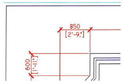
- In the Modify Dimension Style dialog box, Alternate Units tab, click Display Alternate Units.
- In the Unit Format list, select Architectural Stacked.

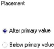
- Under Placement, select Below Primary Value. Click OK.
- In the Dimension Style Manager, click Close to exit the dialog box.
- To update the layout annotative scale:
- Click the layout tab to return to the drawing layout.
- Click to select the viewport border.
- On the status bar, Annotation Scale list, click 1:50.
Note: You may need to click another scale then click 1:50 to get the viewport scale to reset.
- On the status bar, VP Scale, click to lock the viewport.
The dimensions now appear at the correct size in relation to the size of the sheet and the viewport.
Note: The dimension update may take several seconds to appear.
- Zoom to the drawing extents.
- Close all files without saving.