
Exercise | Create Ellipses
In this exercise, you use the Ellipse command to create two full ellipses using two different techniques, trim one of the ellipses so that it becomes an elliptical arc, and then create an elliptical arc with the Ellipse command.
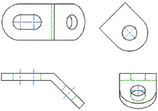
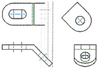
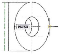
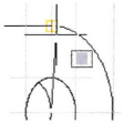
The completed exercise
Completing the Exercise
To complete the exercise, follow the steps in this book or in the onscreen exercise. In the onscreen list of chapters and exercises, click Chapter 11: Creating Additional Drawing Objects. Click Exercise: Create Ellipses.
![]()
- Open C_Ellipse.dwg.
- Zoom into the unfinished area of the top view.
- To create an ellipse to represent the top of a hole from the inclined surface:
- On the Home tab, click Draw panel > Ellipse.
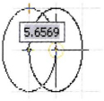
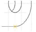
- Click the first point at the bottom intersection, as indicated by the bottom arrow in the following image.
- Click the second point at the top intersection, as indicated by the top arrow in the image.
- Click the third point at the right intersection, as indicated by the right arrow in the image.
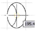
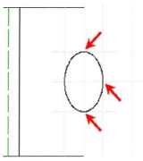
- To create an ellipse to represent the bottom of the hole from the inclined plane:
- On the Home tab, click Draw panel > Ellipse.
- Right-click. Click Center.
- Click the intersection on the left of the previous ellipse, as shown.
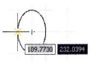
- Move the cursor straight up and click at the intersection.
- Click at the center of the first ellipse.
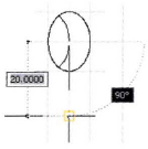
- To trim part of the second ellipse:
- Start the Trim command.
- Click the first ellipse as the cutting edge.
- Click the far left side of the second ellipse as the object to trim.
The left ellipse is trimmed to an elliptical arc, as shown.

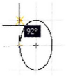
- To create an ellipse in the top view to represent the outer edge of the inclined surface:
- On the Home tab, click Draw panel > Ellipse.
- Right-click. Click Arc.
- Right-click. Click Center.
- Click the center of the first ellipse.
- To define the endpoint of the first axis, snap to the end of the horizontal line.
- To define the endpoint of the second axis, snap to the intersection on the right.
- To specify the start angle, snap to the end of the horizontal line.
- To specify the end angle position, snap to the end of the horizontal line on the top.
- Freeze layer construction. Zoom to display your completed drawing.
- Close all files. Do not save.
..................Content has been hidden....................
You can't read the all page of ebook, please click here login for view all page.