
Exercise | Stretch Objects
In this exercise, you use the Stretch command to increase the area of the rooms in the floor plan. When you have finished, you will be able to use the Stretch command to stretch geometry in other drawings.
The completing exercise
Completing the Exercise
To complete the exercise, follow the steps in this book or in the onscreen exercise. In the onscreen list of chapters and exercises, click Chapter 5: Altering Objects. Click Exercise: Stretch Objects.
![]()
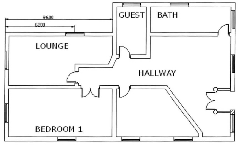
- Open M_Stretch-Objects.dwg.
- On the status bar, turn Osnap off.
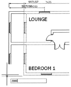
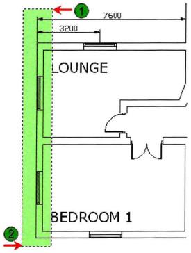
- To add 2000 units to the left side of the structure:
- To complete the stretch operation:
- Click to select near the bottom corner of the wall and drag the cursor to the left 180 degrees.
- Enter 2000. Press ENTER.
- Notice that the dimensions also update to reflect the new size.
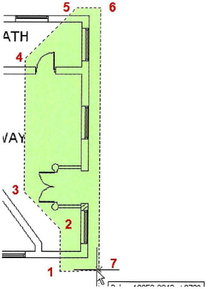
- To use stretch with a Crossing Polygon selection:
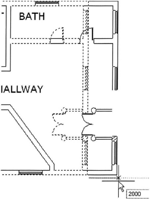
- To add 2000 units to the right side of the structure:
- Press ENTER to complete the crossing polygon selection.
- Press ENTER to complete the object selection.
- Click a point near the bottom corner of the wall.
- Drag your cursor to the right at o degrees and enter 2000. Press ENTER.
- To use stretch with a crossing selection:
- Right-click anywhere in the drawing.
- Click Repeat Stretch.
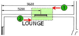
- Enter C. Press ENTER for a crossing window.
- Click near point (1) and then point (2) to define the crossing window. Press ENTER.

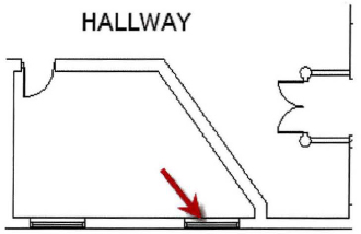
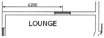
- To slide an interior wall 1500 units to the right:
- Click a point below the floor plan, and then drag to the right at o degrees.
- Enter 1500. Press ENTER.
Notice how the window object moved with the stretch operation. This occurred because any geometry that is fully enclosed by the stretch window is moved rather than stretched.
- To select a window to move within a wall:
- To complete the move:
- Click a point to the right of the window, and then drag to the right at o degrees.
- Enter 1000. Press ENTER.
Notice how the window object moved with the stretch operation and the dimension updated to reflect the new window location.
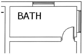
- To select a door to relocate within a wall:
- Start the Stretch command.
- Click near point (1) and then point (2) to define the crossing window.
- Press ENTER.
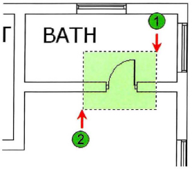
- To relocate the door:
- Close all files without saving.
..................Content has been hidden....................
You can't read the all page of ebook, please click here login for view all page.