
Lesson 01 | Navigating the Working Environment
This lesson describes the working environment and the types of interface elements that you must become familiar with if you are to become proficient in the software.
Before you begin creating drawings, you should familiarize yourself with the interface.
After completing this lesson, you will be able to start the application, activate the appropriate workspace, and identify key parts of the interface.
The following image identifies key interface elements:
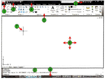
| Application Menu | |
| Quick Access Toolbar | |
| Info Center | |
| Title Bar | |
| Ribbon | |
| Drawing Area | |
| Crosshairs | |
| Command Window | |
| Status bar |
Objectives
After completing this lesson, you will be able to:
- Describe and set the workspace.
- Identify and use keyboard functions.
- Identify key parts of the interface.
- Use the shortcut menu to access commands and options.
- Explain the purpose of AutoCAD-specific interface tools.
Setting the Workspace
Introduction
You launch AutoCAD® in the same way you launch other Windows applications, using one of the following two methods:
- Double-click the AutoCAD 2010 icon on the Windows desktop.
- Click Start > All Programs (or Programs) > Autodesk > AutoCAD 2010 > AutoCAD 2010.
Depending on the options chosen during installation or the status of AutoCAD when it was last closed, you may need to adjust the active workspace.
Warning
If using AutoCAD LT®, select the icon and start menu options associated with AutoCAD LT.

Workspaces Defined
When you launch the application, the interface elements displayed are only those associated with the active workspace. A workspace is a task-oriented drawing environment oriented in such a way as to provide you with only the tools and interface elements necessary to accomplish the tasks relevant to that environment.
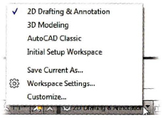
By default, AutoCAD has four workspace configurations:
- 2D Drafting & Annotation
- 3D Modeling
- AutoCAD Classic
- Initial Setup Workspace
AutoCAD LT has two workspaces, one workspace named 2D Drafting & Annotation, the other named AutoCAD LT Classic.

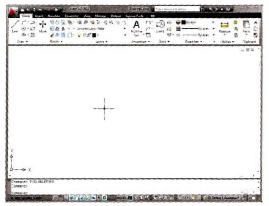
AutoCAD is shown here with the 2D Drafting & Annotation workspace active.
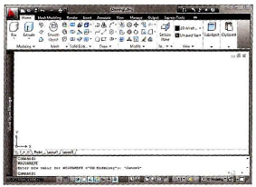
AutoCAD is shown here with the 3D Modeling workspace active.
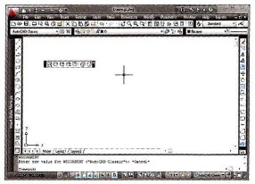
AutoCAD is shown here with the AutoCAD Classic workspace active.
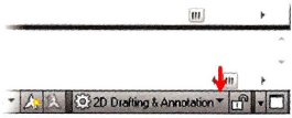
After you start the program you can switch to the desired workspace. The application will open with the last workspace used. The Workspace Switching drop-down list is accessed in the lower right corner of the AutoCAD window on the status bar.
Procedure: Setting the 2D Drafting & Annotation Workspace
The following steps give an overview of activating the 2D Drafting & Annotation workspace.
- Start AutoCAD.
- Use the default drawing or on the Quick Access toolbar, click New.
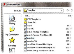
- Select acad.dwt (imperial) or acadiso.dwt (metric) as the template file.
- Click the Workspaces settings icon, located at the bottom right corner of the AutoCAD window. Select 2D Drafting & Annotation.
Procedure: Setting the AutoCAD LT Workspace
The following steps give an overview of activating the AutoCAD LT 2D Drafting & Annotation workspace.
- Launch AutoCAD LT.
- On the Workspaces toolbar, select 2D Drafting and Annotation from the list.
- Start a new drawing and select acadlt.dwt (imperial) or acadltiso.dwt (metric) as the template file.
Note
The instructions and exercise steps covered in this course are based on the 2D Drafting & Annotation workspace. Please activate this workspace if you have not already done so.
![]()
Keyboard Input
Using the keyboard is familiar to everyone who works with computers. For much of the work that you do in AutoCAD you use the keyboard, but you use a few keystrokes more often than others.
Special Keys
You use the following keys most often. These keys have special meaning to the software.
- Use the ESC key to cancel all current actions and return to the Command: prompt.
- Press the ENTER key following all keyboard input. You also complete many commands by pressing ENTER.
- Pressing the SPACEBAR is equivalent to pressing the ENTER key and is often easier to use.
- Pressing the SPACEBAR or ENTER at the Command: prompt repeats the last command used.
- Pressing the UP and DOWN arrow keys will cycle through previous commands used.
- The TAB key is especially useful to navigate in a dialog box. You should use the TAB key to move from field to field. Be careful not to press ENTER.
Function Keys
The use of each of the function keys can be duplicated in other ways with the exception of F2. You may find that the on-screen equivalents to the function keys are easier and allow you to keep your eyes on the screen.
User Interface Layout
There are interface elements common to other Windows applications such as ribbon panels, toolbars, and menus. If you have used other Windows applications, these user interface elements should appear familiar. However, there are interface elements such as the command line and the status bar, which are unique to AutoCAD.
Heads-up Design Defined
Heads-up design is a methodology intended to increase your efficiency while using the software. Whenever you turn your visual focus away from your design to locate a tool, it slows you down. Instead, you should use the most efficient access methods such as Dynamic Input, right-click shortcut menus and the ribbon control panels whenever possible.
Ribbon Defined
The ribbon is a special tool palette associated with each workspace containing only the tools and controls relevant to that workspace. For example, the ribbon for the 2D Drafting & Annotation workspace contains tools relevant to 2D drawing, dimensioning, and annotating, but does not contain tools for 3D geometry creation.
The ribbon supports the heads-up design process because it is space efficient and eliminates the clutter of tool palettes and toolbars. Using the ribbon alone provides you with more space on your screen in the drawing area and enables you to maintain access to the tools and controls you need.
Ribbon Controls
The ribbon is turned on by default when you start the software in either the 2D Drafting & Annotation or the 3D Modeling workspace. The ribbon is organized into a series of tabs. Each tab includes a different set of panels with related commands and controls that may be found on the Classic AutoCAD toolbars and dialog boxes.
You can turn the tabs and associated panels on the ribbon on or off by right-clicking on the ribbon area and selecting Tabs or Panels to select the desired options. You can also turn panel titles on or off by right-clicking the Panel tabs. Additionally, you can save your ribbon configuration.
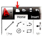
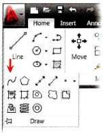
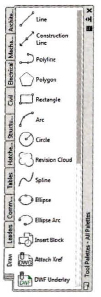
Each tab on the ribbon has its own set of panels that contain groups of related tools, such as those used for 2D drawing, adding text, or adding dimensions. Some panels can be expanded to display more tools. Likewise some tools can be expanded for more options, such as the Circle tool as indicated by an arrow in the corner of the icon.
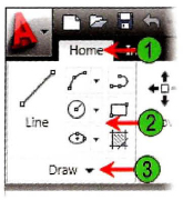
| Tabs: Identifies the purpose and name of the control panel. | |
| Panels: Contains groups of related tools associated with the selected tools. | |
| More Tools: Click and hold the down arrow to display more tools and options in the selected panel. |
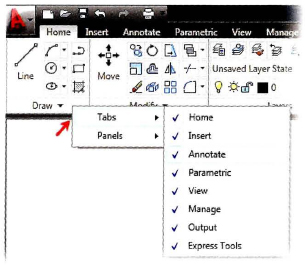
Add or Remove Tabs
To turn specific tabs on or off, right-click in the ribbon and select Tabs. Choose to display or remove tabs from the ribbon. Tabs currently displayed are indicated with a check mark.
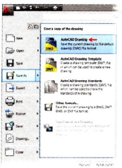
Application Menu
You can use the Application menu to access several key commands such as New, Open, Save, Print, and Close. Most of these commands lead to submenus that give you more detailed options.
Panels
AutoCAD uses ribbon panels as one means to access commands and settings. Similar tools commands are grouped together in panels and can be accessed by clicking the button or icon that indicates the tool's purpose. Each panel consists of a collection of tools that performs related or similar tasks.
When using the 2D Drafting & Annotation workspace, a standard set of panels is displayed on each of the standard set of tabs located on the horizontal ribbon at the top of the AutoCAD drawing area. Notice that when you select a different tab, a different set of panels is displayed.
By default, each panel is docked at the top of the drawing area on the ribbon. You can move the panels away from the docked position to a floating position or drag them back into the ribbon.
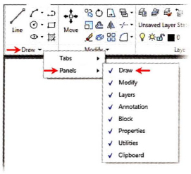
Panel Visibility
To turn specific panels on or off, right-click in the ribbon and select Panels. Select to display or remove panels from the ribbon tab. Panels currently displayed are indicated with a check mark, as shown in the illustration on the right.
Panels will appear in the last position (docked or floating) they were in before the panel was removed from the display.
Tip
When you click icons on the ribbon panel, the command is not executed unless the cursor is over the icon when you release the mouse button. If you click the wrong icon, simply drag the cursor away from the button before releasing.

Panel Tools Visibility
Some panels will cascade to reveal additional tools when you select the black arrow in the lower right-hand corner of the panel. You can keep these panels open to display all of the tools by selecting the thumbtack located in the lower left-hand corner of the cascading panel.
Status Bar
The status bar is located at the bottom of the application window.
The left end of the status bar displays the coordinates that show the numerical position of the crosshairs in the drawing. Click this area to turn the coordinate display off or on. In the on position, there are two possibilities. The readout displays the X, Y, and Z values, or the distance and polar angle of the crosshairs as it is moved in the drawing window.
![]()
Coordinates Display
To the right of the Coordinates Display, there are buttons that activate features to facilitate drawing construction. Collectively, these features are termed drafting settings.
![]()
Drafting Settings
In the middle-right of the status bar are buttons to display the drawing model or the drawing layout views.
![]()
Model Space and Layout Settings
To the right of the Model Space and Layout buttons are the realtime Pan command and the Zoom command.
Pan and Zoom
Towards the right side of the status bar are the Annotation options for the display of annotative objects such as text and dimensions. When you create annotations with the annotative property selected, the Annotation Scale displayed in the status bar represents the scale in which the new objects are created.
![]()
Annotation Settings
About Shortcut Menus
The shortcut menu is context-sensitive. When you right-click in the graphics window, you can use the options presented on the shortcut menu to perform a variety of tasks. Context-sensitive means that the menu will change depending on what you are currently doing in the software. For example, if you are at the command prompt your shortcut menu will have different options available than if you are in the Pline command.
Definition of Shortcut Menu
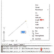
Shortcut menu options are organized into different areas. The options that are made available to you are based on the current context of your work and will change when you activate the shortcut menu. The following image shows the shortcut menu as it appears when you are creating a polyline.
The top area of the menu offers Enter, Cancel, and Recent Input options.
The middle area of the menu offers options specific to the current command. Notice how the options on the menu match the options on the command line. To use an option for a command, select the option on the shortcut menu. This has the same effect as entering the capital letter(s) of the option on the command line.
The lower area of the menu offers Pan and Zoom functions and access to the QuickCalc command.
Key Points
- The shortcut menu is context-sensitive, so its options differ depending on the current context of the software, for example, whether you are drawing or editing.
- You can use the shortcut menu as an alternative to entering command options on the command line. This speeds up the design process and is the preferred method for working with suboptions of the active command.
More AutoCAD-Specific Interface Tools
While the software complies with Windows standards for user interface elements, there are some element types that are specific to the application.
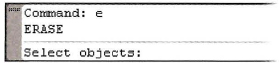
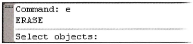
The following image shows the command window. Somewhat unique to a graphical windows application, the command window provides another method for the user to interact with the application.
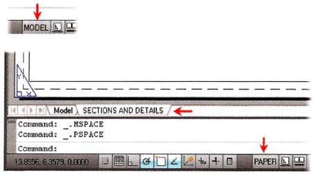
Layouts (Drawing Sheets)
Model space (the Model tab) is the area where you create your designs. Layouts (drawing sheets) are for annotation, borders, title blocks, and plotting.
When you design, you should always draw at full scale. The model space environment offers an unlimited amount of space to create your designs. Use layouts to create drawing sheets that represent an area equal to the actual size of the paper.
You can switch between model space and the Layout by selecting the button located in the status bar at the bottom of the AutoCAD window.
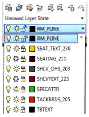
Layer List
The Layer list displays the drawing's layers. Using this list, you can switch the current layer, assign selected objects to a layer, turn layers on and off, freeze layers, and lock layers.
Tool Palettes
Tool palettes simplify the task of adding predefined design content to your drawing.
The tool palettes are a set of overlapping panels contained in a floating window. For easy identification, they are grouped by tabs.
The palettes provide an efficient method for organizing, sharing, and placing area fill patterns and symbols that you use regularly.
You can customize the individual tools on the palettes by setting properties that are specific to the object, such as scale, rotation angle, or a predefined color.
Palettes can also contain custom tools provided by third party developers.
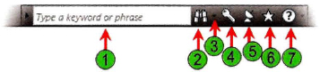
InfoCenter Defined
The InfoCenter, located to the far right of AutoCAD title bar, consists of the InfoCenter search and access to the Communication Center panel. You can use the InfoCenter search by typing in key words or by typing a question. While there are many locations for which InfoCenter can be configured, the following locations are provided as examples:
- User's Guide
- Command Reference
- New Features Workshop
The InfoCenter is shown in the following illustration.
![]()
Communication Center
The Communications Center, accessed through the InfoCenter menu bar, provides real-time notifications, announcements, and news to your desktop. You must be connected to the Internet to take advantage of this feature. The following is a partial list of information sources you can access:
- New Software Updates
- Product Support
- CAD Manager Channel
- RSS Feeds
Access
Communication Center Options
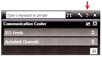
Expand the Communications Center title bar to see all of the configured Autodesk channels.
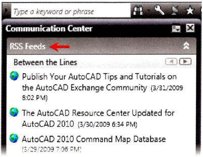
Expand the RSS Feeds title bar to see all of the configured RSS feeds. By default, several RSS feeds are created for you when you install AutoCAD.
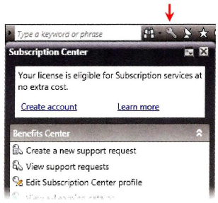
Select the Subscription Center button to view all of the configured Subscription Center items, such as product support requests and e-Learning catalogs and lessons (Available to subscription customers only.).
Command Window
The command window is normally located at the bottom of the application window and docked between the drawing area and status bar. Whether you enter a command manually at the command line or click a command tool on a toolbar, all commands are passed through and evaluated by the command line.
It is important that you monitor the activity that occurs in this area. At each stage of the command process, the software either provides you with a series of options to choose from or requires that you input values relevant to that stage of the process.
In normal operation, the command window contains three lines of text. The first two lines list the immediate command history and display the settings or options available within the current command. The bottom line is the command line. You should focus your attention here during the majority of commands.
You type at the cursor position on the command line, that is, the command prompt.
Note: Always press ENTER after you enter values on the command line.
Although the command window is usually docked at the bottom of the drawing window, you can move it freely around the drawing. You can dock it to the edge of the application window or leave it floating over the drawing area. Click and drag the vertical bars to the left of the command window to place it in a floating position over the drawing area.

Tip
While floating the command window over the drawing area can partially obstruct your view, you may benefit from this configuration because it serves as a reminder to monitor the command window.
Command Sequence
The process of entering command sequences is straightforward but important. To use the software successfully, you must become comfortable with typical command sequences such as the following one for drawing a circle.
- Circle
- Specify center point for circle or [3P/2P/Ttr (tan tan radius)]: Select a point or enter a coordinate.
- Specify radius of circle or [Diameter] <25.0000>: d (Use a command option).
- Specify diameter of circle <50.0000>: 75 (Enter values when prompted).
If you spend enough time working with the software and paying attention to the command line and other interface elements, you will soon know what information is required without even looking at the command line.
Help Menu
Before you explore the software any further, you should familiarize yourself with the extensive Help documentation provided.
The Help menu provides access to the Help system as well as online resources for Knowledge Base, Training Resources, and the Autodesk User Group International (AUGI). You can also find out more information about and volunteer to participate in the Customer Involvement Program.
