Lesson 04 | Inputting Data
Every drawing action requires some form of data input. Regardless of the types of geometry you create, you are constantly inputting data in one form or another.
In this lesson, you will learn to input data using the command line, dynamic input, direct distance entry, shortcut menus, and the Cartesian coordinate system. You will use the concepts you learn in this lesson in exercises throughout this course.
After completing this lesson, you will be able to use the command line, explain different types of coordinates, activate and use the Dynamic Input interface, use direct distance to enter values, and use the shortcut menu to access commands and options.
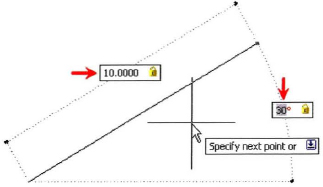
The following image illustrates how to use the Dynamic Input interface to draw a 10 unit line at 30 degrees.
Objectives
After completing this lesson, you will be able to:
- Use the command line to enter commands and command options.
- Explain the difference between a Cartesian and a polar coordinate, and between an absolute and a relative coordinate.
- Activate the dynamic input interface and list key points about using it.
- Create and edit geometry using the dynamic input interface.
- Use direct distance entry to enter distance values.
About the Command Line
There are specific AutoCAD elements such as the ribbon, menus, and other tools that are common to all Microsoft Windows applications. However, the command line interface is unique to AutoCAD.
Most commands have options with which you can control various aspects of how the command is used. You should pay attention to the command line as you work.
Command Line Defined
The command line is the primary place where you communicate with the software. On the command line, you are prompted to input information.
Command Line Options
- Command options appear on the command line. The capitalized letter(s) represents the letter(s) you enter to use that option. You are not required to enter the letter(s) as a capital letter.
- Options for the command appear within […] brackets. If there is a default option for the command, it appears within <…> brackets. To use the default option, press ENTER.
- Press the F2 key to display the full command window. Each command that you use during your drawing session is saved here. Press F2 again to close the full command window.
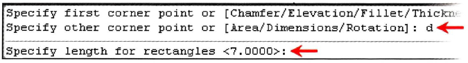
The following image shows command line options and a command line default value. In this situation, the user has started the rectangle command, and has entered d for the Dimension option. After pressing ENTER, a default distance of 7.0000 is displayed. If the user does nothing but press ENTER, a value of 7.0000 is used.
Command Line Example
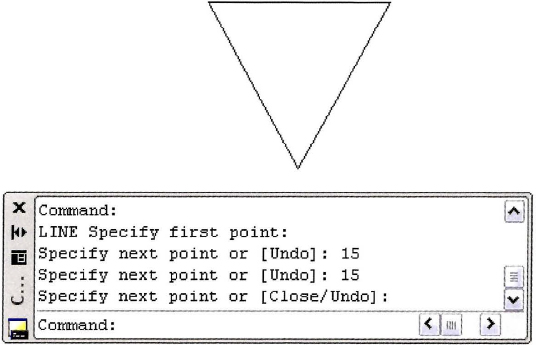
The following image shows a typical command and its options as they are presented on the command line. The last line shows the current status of the command. The previous lines show the command line history.
About the coordinate System
Every object you draw is placed in either the world coordinate system (WCS) or a user coordinate system (UCS). When you create 2D geometry, data input is ultimately passed to the software in the form of Cartesian (x, y) or polar coordinates (distance, angle). You can either manually enter these coordinates or infer them by picking a point in the drawing window.
Cartesian coordinate System
Every object you draw is placed in either the World coordinate System (WCS) or a User coordinate System (UCS). When you create 2D geometry, data input is ultimately passed to the software in the form of Cartesian (x, y) or polar coordinates (distance, angle). You can either manually enter these coordinates or infer them by picking a point in the drawing window.
The Cartesian coordinate system is used to determine points in space that are a specified distance from a set of perpendicular axes that intersect at the origin of the system.
In the World coordinate System, the X axis represents the horizontal direction, the Y axis represents the vertical direction and the origin is located at 0,0. Positive X moves to the right, positive Y moves up, and the Z axis moves in the positive direction directly towards you, the viewer.
Note that for this course we will only be concerned with the X & Y coordinates since we are working in 2D. The Z coordinate will always be zero and need not be specified.
The following image illustrates a line drawn from the origin of the coordinate system 0,0 with its endpoint at the coordinate 4,6.

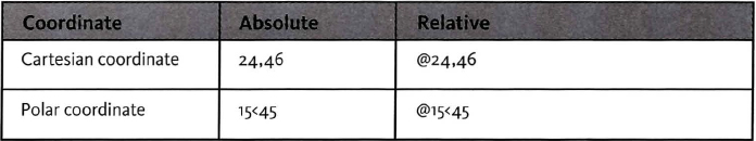
To specify a Cartesian coordinate, enter the X and Y coordinates and press ENTER. Example: 4,5 where X is equal to the distance from the origin along the X axis and Y is equal to the distance from the origin along the Y axis.
Polar coordinates
A polar coordinate is a point in the coordinate system that is determined by a distance and an angle.
The following illustration shows a line drawn from the origin of the coordinate system with a length of 7 units and an angle of 45 degrees.
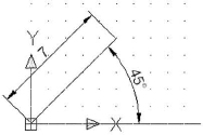
To specify a polar coordinate, type the distance < angle, example 5<45, where Distance equals the distance traveled from the specified origin point and Angle equals the angle from the X axis.
Polar Angle
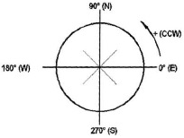
The default polar angle is measured counterclockwise from the zero angle position. The default zero angle is in the East compass direction.
The following illustration shows how angles are defined with a polar coordinate. This angle measurement applies to entering coordinates, working with arcs, and rotating objects.
Absolute and Relative coordinates
When you enter coordinates, they can be in the form of an absolute or a relative coordinate.
- An absolute coordinate represents a specific point in the current coordinate system relative to the origin point (0,0). To enter an absolute coordinate, enter the values as a Cartesian coordinate (x, y) or Polar coordinate (distance angle).
- A relative coordinate is a point located from a previously selected point. To enter a relative coordinate, select your first point, then precede the next coordinate point with the @ symbol. For example @5<45 would mean 5 units at 45 degrees from the last point selected, and @3,5 would mean 3 units in the positive X direction and 5 units in the positive Y direction from the last point selected.
Note that when the Dynamic Input option is selected in the status bar, relativity is automatically assumed.
Entering coordinates
- You can enter coordinates any time the software is in point acquisition mode, that is, when the command line is prompting you to specify a point or distance.
- Every drawing contains the world coordinate system (WCS). The WCS is identical in every drawing and cannot be altered. For example, an object placed at the absolute coordinate 10,10 would be positioned in the same location in any drawing.
- Unless you specifically define a User coordinate System, all geometry you create is drawn relative to the WCS.
Tip
The UCS icon displays differently when you are working in the world coordinate system versus a user coordinate system. The UCS icon for the world coordinate system contains a small box at the origin of the X and Y axes.

Absolute and Relative coordinate Examples
Example of Cartesian coordinate Input
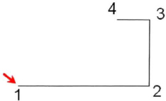
The following lines could have been drawn using Cartesian or Polar coordinates. Assuming the start point at the red arrow, the command line input for relative Cartesian or Polar coordinates would be as follows:
Point 2: @4,0 or @4<0
Point 3: @0,2 or @2<90
Point 4: @-1,0 or @1<180
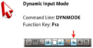
About Dynamic Input
The Dynamic Input interface is a way of entering data dynamically. Rather than entering data on the command line, which is generally positioned at the bottom of the screen, you can use the Dynamic Input interface for heads-up design, entering command information on screen at the cursor location.
Using the Dynamic Input Interface
The Dynamic Input interface is context sensitive based on the current operation. For example, the input and options are different when you are drawing a line than when you are drawing a circle; they also differ based on whether you are creating or editing geometry.
Dynamic Input Interface: Dimensional Input Mode
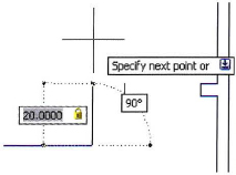
There are two Dynamic Input interface modes: Dimensional Input and Pointer Input. The following image represents the Dynamic Input interface in Dimensional Input mode. This mode is available when the Dynamic Input option is selected in the status bar and is commonly used for the typical drawing commands such as Line, Circle, and Arc.
Note: Numbers in the following image correspond to the numbers in the list below.
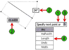
1. Tooltip: Displays instructions for the current step in the command and also reflects the current prompt on the command line.
2. Coordinate, Length, or Angle input fields: Depending on the mode, these fields may vary in value and position. In the image, one field represents the current length of the polyline while the other represents the angle of the cursor. Enter a value to specify an explicit value. Press TAB to cycle between the fields.
3. Down Arrow: Press DOWN ARROW (on the keyboard) to display the Dynamic Input menu. Press UP ARROW to cycle through previously selected coordinates.
4. Dynamic Input Menu: Select an option for the command. Available options vary based on the current context and reflect the options available on the command line.
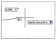
Dynamic Input Interface—Pointer Input Mode
In the following illustration, the Dynamic Input interface has changed to Pointer Input mode because the values @ 10 < 45 were entered on the keyboard. In Pointer Input mode, you can enter coordinate information at the pointer as though your focus were on the command line. Use this mode for absolute and relative coordinates. It is also the default mode for commands such as Move, Copy, and Rotate.
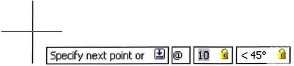
Lock icons indicate a value that has been manually entered. To unlock a value, press TAB to enter the input field, press DELETE to clear the value, then press TAB to exit the input field.
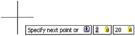
The default mode for dynamic input is for relative coordinates, but you can also enter absolute coordinates. To do so, enter a pound sign before the first coordinate, for example, #2,20. If you enter 2,20 (without the # sign), the point will be relative to the last selected point. The dynamic input fields adjust to reflect the entry format. In this case, the second field represents the Y coordinate.
Dynamic Input Options
Use the Dynamic Input tab in the Drafting Settings dialog box to change settings related to the Dynamic Input interface.
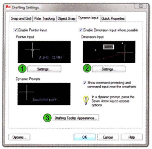
| Click to adjust Pointer Input options. | |
| Click to adjust Dimensional Input options. | |
| Click to adjust appearance-related options for the Dynamic Input tooltips. |
Guidelines for Using Dynamic Input
- When you use grips to stretch objects, or when you create new objects, dimensional input displays only acute angles; that is, all angles are displayed as 180 degrees or less. Thus, an angle of 270 degrees is displayed as 90 degrees. Angles that you specify when creating new objects rely on the cursor location to determine the positive angle direction.
- Dynamic Input is not intended to replace the command window. You use both the dynamic interface prompts and the command line in your workflow.
- The Dynamic Input interface is context sensitive.
- When Dynamic Input is on, points that you enter in response to second or next point prompts default to relative.
- Depending on the location of the cursor and the status of other settings such as object snaps, polar tracking, and tooltips, other information may appear on the Dynamic Input interface including object snap tips and command line prompts.
Using the Dynamic Input Interface
You can use the Dynamic Input interface in several ways, but the primary goal of the tool is to let you draw and edit in a heads-up mode, with your focus on the graphics window instead of the command line. Because the Dynamic Input interface is context sensitive, its options and display modes are dependent on the context in which you are working. The following guidelines give an overview of how you can use the Dynamic Input interface during typical drawing and editing tasks.
Command Access
Procedure: Drawing with Dynamic Input
The following steps give an overview of creating geometry using the Dynamic Input interface and Polar coordinates. Note that because the Dynamic Input display is activated, relativity is assumed and it is not necessary to enter the ampersand symbol (@).
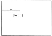
- Begin a command. The Dynamic Input field displays the command.
- After you press ENTER, the interface immediately switches to Point Input mode. The tooltip gives instructions for what is required and the input fields reflect the current XY coordinate location of the cursor.
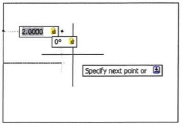
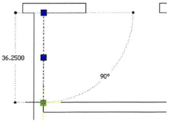
- The Dynamic Input display prompts you for the next point. Enter a value in the Distance input field and press TAB to lock the distance and activate the Angle input field. Enter a value in the Angle input field and press TAB to lock the angle at 0 degrees. Click to select the point.
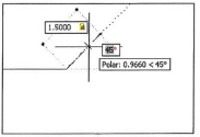
- Enter another value in the Distance input field and press TAB to lock the distance. Move the cursor to adjust the angle value shown, but note that if you simply click, the angle is rounded up to the nearest whole number as determined in the Units settings. It would be best to enter the angle for accuracy.
- Click the final point and press ENTER to complete the line.
- Your finished object is shown.


Procedure: Editing with Dynamic Input
The following steps give an overview of some of the ways you can edit with the Dynamic Input interface.
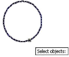
- On the Home tab, click Modify panel > Copy. Select the objects to be copied and press ENTER to complete your selection.
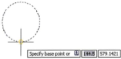
- The Dynamic Input interface prompts you to Specify a base point. Notice the blue down arrow. Using the arrow keys on your keyboard, you may switch to single copy mode or multiple copy mode. Select a base point on or near the object.
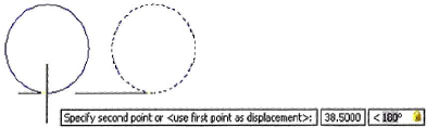
- The Dynamic Input tooltip provides feedback. Entering @38.500<180 puts the interface in Relative coordinate mode and places the values in the correct input fields. Press ENTER to complete the Copy command.
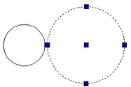
- Select the circle to activate the grips.
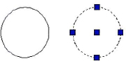
- Select a quadrant grip to display the Dynamic Input interface. Grip editing displays several options. You can resize the circle either by entering a new radius (1), or TAB for one of the other options to increase or decrease the radius (2). Enter a value in one of the input fields and press ENTER.

The circle is resized.
Using the Dynamic Input Interface to Reveal Information
You can see the length or angle of a line or the radius of an arc or circle by using the object grips. With the command line blank, select the geometry to activate the grips. Hover the cursor over one of the end grips or circle quadrants without selecting the grip. The Dynamic Input interface displays size information for the selected geometry.
Guidelines for Using Dynamic Input
- When entering length or angle, press TAB to lock the values.
- Before entering the length or angle, you may press TAB to cycle through the available input fields. Enter the desired values and press ENTER to complete the command.
- To reveal the length or angle of a line, or the radius of an arc or circle, select the geometry (with the command line blank) to activate the grips. Hover the crosshairs over one of the grips. The Dynamic Input interface displays size information for the selected geometry.
- To Modify an object using Grips, select the object (with the command line blank) and then select a grip. Press TAB to cycle through the available fields. Supply the desired data and press ENTER.
- When Dynamic Input is on, points you enter in response to second or next point prompts default to relative.
- To enter XY coordinate values, press # to switch to absolute coordinate entry mode.
Using Direct Distance Entry
Direct distance entry is by far the easiest and quickest way to enter data while using the Draw and Modify commands. You can enter a distance value whenever the software prompts you to select a point. The point coordinates are calculated based on the angle of the cursor from the previous point selected and the distance you enter. It is a good idea to have Polar Tracking on when using this method.
You may use this method of data entry whether the Dynamic Input mode is on or off.

Guidelines for Using Direct Distance Entry
- Turn Polar Tracking on to display the cursor's angle.
- Set the desired incremental polar angles in Polar Tracking settings.
- Enter the desired distance and press ENTER. Be sure that the accurate Polar angle is displayed.
- AutoCAD is accurate 14 places to the right of the decimal point (1.00000000000000). Therefore, it is important to enter the distance and use Polar Snap for absolute precision.
- Although turning Dynamic Input off limits the data fields displayed by your pointer, you may use Direct Distance entry with this feature on or off.
Procedure: Using Direct Distance Entry
The following steps give an overview for using the direct distance entry method.
- Start a command such as Line and click a point to begin. Tip: Toggle off Dynamic Input on the status bar for clearer results.
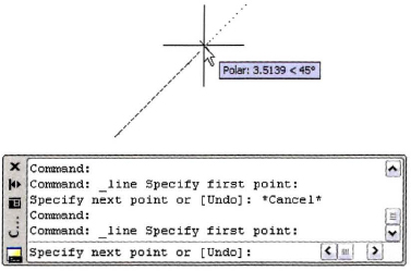
- When you are prompted to specify the next point, drag your cursor in the direction you want the line to travel, enter a distance on the command line, and then press ENTER.
Tip: Turn polar tracking on to display the current angle of your cursor.
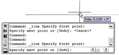
- Drag the cursor in the direction of the next line segment, enter a distance value, and press ENTER.
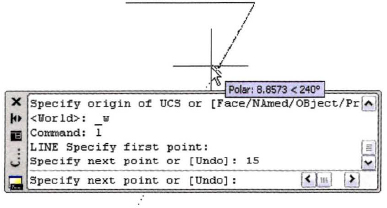
- Repeat step 2 until the geometry is completed.
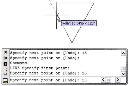
- Press ENTER to exit the command. Your object is completed.