
Exercise | Edit Dimensions
In this exercise, you edit dimensions by adjusting their placement, adding text to the default dimension value, and creating a new dimension substyle for diameter dimensions.
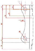
The completed exercise
Completing the Exercise
To complete the exercise, follow the steps in this book or in the onscreen exercise. In the onscreen list of chapters and exercises, click Chapter 8: Dimensioning. Click Exercise: Edit Dimensions.
![]()
- Open M_Edit-Dimensions.dwg.
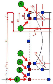
- To use grip editing to move a string of dimensions:
- Select the string of continuous dimensions in the left view of the drawing.
- Press SHIFT+select on the five grips indicated (1), (2), (3), (4), and (5). They turn red.
- Click one of the selected grips (6) and drag the dimensions to the left.
- Press ESC to clear the selection.
- To move dimension text to a new location with the right justify Dimtedit command:
- On the command line, enter dimtedit. Press ENTER.
- Select the 29mm linear dimension indicated (1).
- Right-click anywhere in the drawing. For justification, select Right.
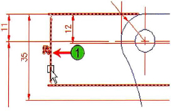
- Repeat the previous step on the 35 mm linear dimension.
- The dimensions should appear as shown.
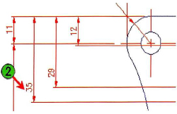
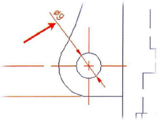
- To relocate dimension text with grips:
- Select the jogged radial dimension.
- Select the grip (1) and drag it to a new
- location as shown (2).
- Press ESC to clear the selection.
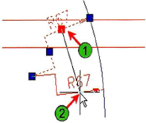
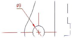
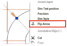
- To flip the arrow of a dimension:
- Locate and view the diameter dimension in the lower left corner of the part.
- To create a diameter dimension substyle:
- On the Annotate tab, click Dimensions panel > Dimension, Dimension Style.
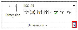
- In the Dimension Style Manager, click New.
- In the Create New Dimension Style dialog box, select Diameter Dimensions from the Use For list.
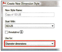
- Click Continue.
This creates a dimension substyle of ISO-25 in which modifications only apply to the diameter dimensions.
- On the Annotate tab, click Dimensions panel > Dimension, Dimension Style.
- To set the text alignment for the substyle:
- In the New Dimension Style dialog box, Text tab, under Text Alignment, select ISO Standard.
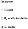
- Click OK.
The new dimension substyle appears under the ISO-25 dimension style.
- In the New Dimension Style dialog box, Text tab, under Text Alignment, select ISO Standard.
- Click Close to exit the Dimension Style Manager. The dimension value is now horizontal as a result of the new dimension substyle.
- Close all files. Do not save.
..................Content has been hidden....................
You can't read the all page of ebook, please click here login for view all page.