
Exercise | Use Object Snap Tracking
In this exercise, you use object snap tracking to create a side view of the part. After completing this lesson, you will be able to use object snap tracking in other drawings.
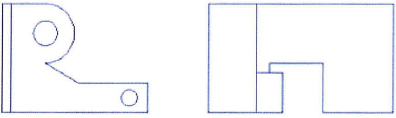
The completed exercise
Completing the Exercise
To complete the exercise, follow the steps in this book or in the onscreen exercise. In the onscreen list of chapters and exercises, click Chapter 2: Creating Basic Drawings. Click Exercise: Use Object Snap Tracking.
![]()
- Open M_Object-Tracking.dwg.
- On the status bar, make sure the following settings are turned on:
- Polar tracking
- Object snap
- Object snap tracking
- Dynamic input
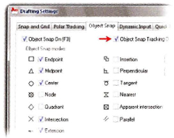
- Right-click Object Snap Tracking. Click Settings.
- In the Drafting Settings dialog box, select the running object snaps as shown in the image. Click OK.
- To draw a rectangle:
- On the Home tab, click Draw panel > Rectangle.
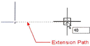
- Acquire the lower right corner of the existing shape and move the mouse to the right along the extension path.
- Enter 40 in the Dynamic Input field. Press ENTER.
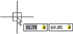
- Move the cursor up and to the right.
- Enter 31.75, 69.85. Press ENTER.
- To repeat the rectangle command:
- Right-click in the graphics window. Click Repeat RECTANG.
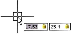
- Select the lower right corner of the previous rectangle as the start point.
- Enter 17.53, 25.4. Press ENTER.
- To draw a line:
- On the Home tab, click Draw panel > Line.
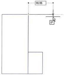
- Select the top right corner of the first rectangle.
- Move the cursor to the right at 0 degrees. Enter 90.55. Press ENTER.
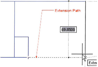
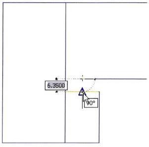
- Move the cursor to acquire a tracking point from the lower right corner of the second rectangle. Track back to the line until the angle shows 90 degrees. Click to select the point.
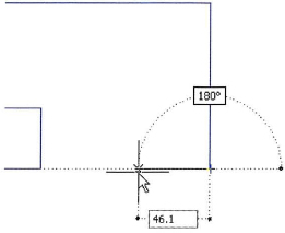
- Move the cursor to the left. Enter 46.1. Press ENTER.
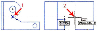
- Acquire the point where the arc and angled line meet (1). Track back to the point where the current line meets the tracking line (2). Click the intersection of the alignment paths.
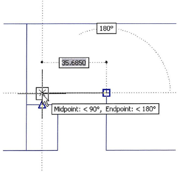
- Acquire the midpoint of the top line of the second rectangle. Track upwards until you get to the intersection of the two tracking lines. Click that point.
- Select the midpoint of the top line of the second rectangle. Press ENTER to complete the line command.
- Close all files. Do not save.
..................Content has been hidden....................
You can't read the all page of ebook, please click here login for view all page.