
Challenge Exercise | Mechanical
In this exercise, you use what you learned about altering objects to edit geometry.
Note: In the following image, the views are closer together than they will appear in your drawing.

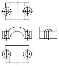
The completed exercise
Completing the Exercise
To complete the exercise, follow the steps in this book or in the onscreen exercise. In the onscreen list of chapters and exercises, click Chapter 5: Altering Objects. Click Challenge Exercise: Mechanical.
![]()
- Open the drawing you saved from the previous challenge exercise, or open M_MECH-Challenge-CHP05.dwg.
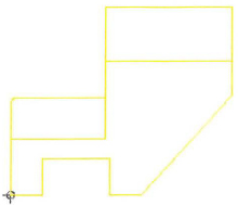
- Create and edit geometry so the views for the Rack Slider Top appear as shown.
Note: The views in the image are closer together than they will appear in your drawing.
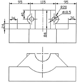
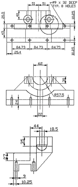
- Create and edit geometry so the views for the Rack Slider Base appear as shown. Use Join to join the collinear lines that were created with Mirror in a previous challenge.
Note: The views in the image are closer together than they will appear in your drawing.
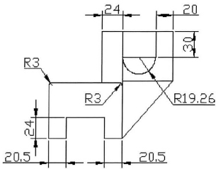
- Create and edit geometry so the side view for the Rack Slider Base appears as shown. Note the 3mm radius fillets.
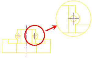
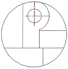
- Copy geometry from the area indicated to the upper-right of the view.
- Scale the resulting geometry to twice its regular size.
- Draw a circle around the scaled geometry, then trim the geometry to the circle.
- Copy geometry from the existing views to create the assembly views. You won't need the hidden and centerlines.
- Thaw the Start Points layer.
- Use the Assembly Start Point to locate the position of the assembly front view.
- Erase geometry as required if it would be hidden by other parts as it is assembled.

- Delete the Assembly Start Point leader and text.
- Create the centerlines for the detail view.
- With the Hidden layer current, create the hidden geometry in these views using points in each view as references. Then create the centerline objects and place them on the Centerline layer. Note: In the following image, the views are closer together than they are in the drawing.
- Copy the geometry for the side view to create a section (you will apply hatching in a later challenge exercise). Move the hidden geometry to the Visible layer, then delete and trim unnecessary geometry. Delete the hole geometry.
- Copy the section view to the start point to the right of the side assembly view.
Copy the Rack Slide Top' s side view and position it on top of the section view, then move hidden lines to the visible layer and remove the unnecessary geometry.

- Save and close all files.
Chapter Summary
Every design you create begins with simple geometry. The procedures you use to edit these basic objects transform them into complex designs.
Having completed this chapter, you can:
- Change the length of objects using the Trim and Extend commands.
- Create parallel and offset geometry in your drawing by using the Offset command.
- Use the Join command to combine multiple objects into a single object.
- Break objects into two or more independent objects.
- Apply a radius corner to two objects in the drawing.
- Apply an angled corner to two objects in the drawing.
- Use the Stretch command to alter the shape of objects in the drawing.