
Exercise | Use Multileaders
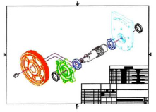
In this exercise, you create a multileader style to add callouts to an exploded view drawing. You then add multileaders to the drawing using different options associated with multileaders.
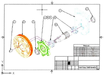
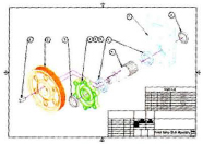
The completed exercise
Completing the Exercise
To complete the exercise, follow the steps in this book or in the onscreen exercise. In the onscreen list of chapters and exercises, click Chapter 8: Dimensioning. Click Exercise: Use Multileaders.
![]()
- Open c_Front-Pump-Assembly.dwg.
- To create a new multileader style:
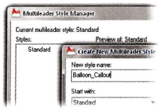
- On the Leaders panel, click the Multileader Style Manager dialog box launcher.
- In the Multileader Style Manager dialog box, click New.
- In the Create New Multileader Style dialog box, New Style Name, enter Balloon_Callout. Click Continue.
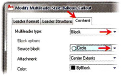
- To assign the Content type:
- Click the Content tab.
- In Multileader Type, select Block from the list.
- Under Block Options, select Circle from the list. Click OK.
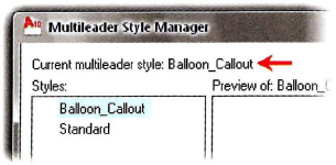
- In the Multileader Style Manager, verify that Balloon_Callout is the current multileader style. Click Close.
- Check the Object Snap Settings to ensure that Endpoint, Midpoint, and Intersection snap modes are selected.
- To place a Multileader:
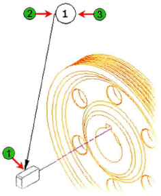
- On the Leaders panel, click Multileader.
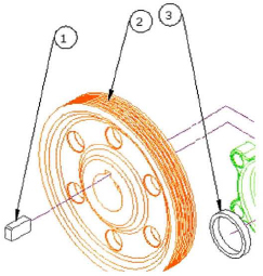
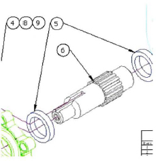
- Using Object Snap, select the Midpoint of the top line of the keyway (1).
- Move the cursor above the pulley and click a location (2).
- Notice the command line. An attribute has been assigned to this block. Enter 1 (3).
- Using the same steps, place a multileader for the pulley and seal as shown. Enter 2 for the pulley and 3 for the seal.
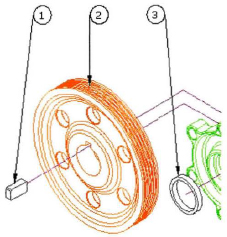
- To align multileaders:
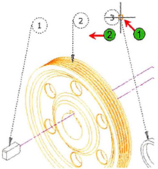
- On the Leaders panel, click Align.
- Use a crossing window to select all three multileaders. Press ENTER.
- Right-click to access the shortcut menu. Click Options. Click Distribute.
- Select a point on the highest multileader (1).
- Move the cursor horizontally with Polar Tracking, indicating that the motion is straight (2). Try not to select an object snap because this may override the horizontal direction.
- Click to align the multileaders.
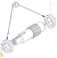
- Place a multileader on the bearing as shown. Enter 5.
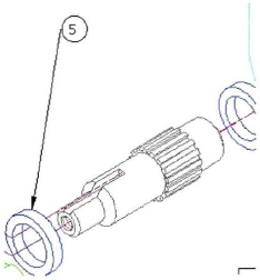
- To add a multileader to an existing multileader:
- On the Leaders panel, click Add Leader.
- Select the number 5 multileader.
- For the second leader arrowhead location, select the bearing at the other end of the shaft. Press ENTER.
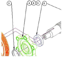
- Add multileaders 4, 8, and 9 to the front pump housing.
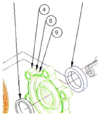
- To collect multileaders:
- On the Leaders panel, click Collect.
- Individually select multileaders 4, 8, and 9 in order. Press ENTER.
- Verify in the Command line that Horizontal is the current option. If not, right-click and select it from the shortcut menu.
- Click to place the collected multileaders.
- To add a multileader specifying content first:
- On the ribbon, Leaders panel, click Multileader.
- Right-click. Click Options.
- Select Content type.
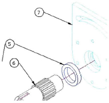
- Click a location below the number 5 callout. Enter 6.
- Locate the arrowhead of the multileader to the shaft.
- To add a multileader specifying the landing first:
- On the Leaders panel, click Multileader. Enter L. Press ENTER.
Note: You can right-click in the Command line or enter the capitalized letter of the command options.
- Click a point to the left of the rear housing to locate the callout.
- Click the rear housing to locate the arrowhead. Enter 7.
- On the Leaders panel, click Multileader. Enter L. Press ENTER.
- Using the options of your choice, add a multileader to the last part in the exploded view. Enter 3.
- Close all files without saving.
..................Content has been hidden....................
You can't read the all page of ebook, please click here login for view all page.