Lesson 43 | Using Blocks
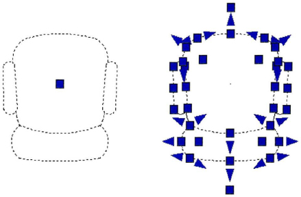
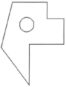
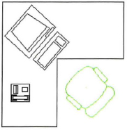
This lesson describes how to create a block definition and insert a block definition or file into a drawing. For example, in the following illustration, the single block object on the left was created from all of the geometry on the right. The block object keeps all of the geometry tied together. The chair on the right is made of individual lines, arcs, and polylines while the objects on the left are a block definition; you can insert them into a drawing as a single object.
Using groups of objects to create block definitions that act as a single object can help you work more efficiently. Multiple objects that are defined as a block increase the reusability of that geometry when you or others use the block in other drawings or locations. Creating blocks to use in other drawings vastly improves overall efficiency and helps you to maintain consistency in your designs.
Objectives
After completing this lesson, you will be able to:
- Describe blocks and how they are used to group objects together.
- Describe the properties that affect block behavior in the drawing.
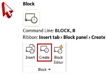
- Use the Block command to create a block definition.
- Use the Insert command to insert a block reference in a drawing.
About Blocks
Blocks provide an efficient way to group a set of objects together and reuse them throughout all of your drawings and projects. You can create your own blocks or use some of the thousands available from others via the Internet.
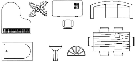
The following illustration shows an example of typical blocks you might use to create an office or home layout drawing.
The following illustration shows an example of typical blocks you might use to create a mechanical or electrical drawing.
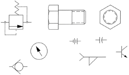
Mechanical symbols
Blocks Defined
Blocks are often referred to as symbols. These symbols are made up from a collection of objects grouped together into a block definition. A block definition can be made from a single object in your drawing or from multiple objects. You only need to draw a symbol once; then, whenever you need that symbol in any drawing, you simply insert it.
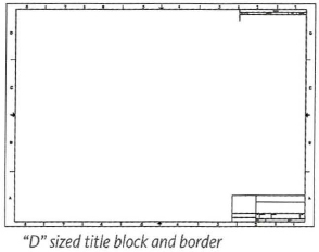
One symbol found in most drawings is a title block and border.
Tracing Analogy
In the days of manual drafting, draftsman used cardboard or plastic templates to trace common items onto their drawing. Some of the most simple were circles and ellipse templates, but mechanical engineers also used templates for arrowheads, bolts, and hydraulic cylinders. Architects traced common fixtures such as sinks, bath tubs, or lavatories. By tracing these templates, draftsmen were able to produce common objects consistently throughout their drawings.
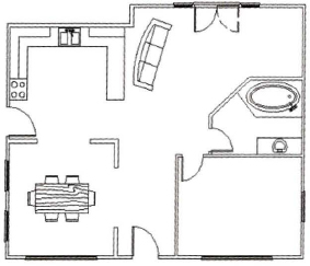
Example: Blocks used for Architectural Drafting
In architectural drafting, blocks are used for common objects, including doors, windows, case goods, plumbing fixtures, and furniture. The following drawing shows a simple floor plan that is made from many blocks.
How Blocks Behave
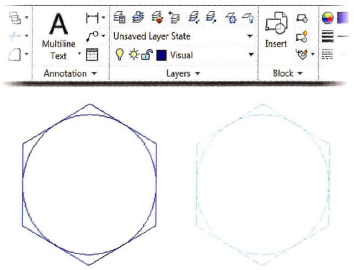
Blocks behave exactly as you want them to, provided you follow the rules for creating them. When you insert a block, the color, linetype, and lineweight of objects in the block retain their original settings regardless of the current settings in the drawings. However, you can create blocks with objects that inherit the current color, linetype, and lineweight settings.
In this image, both blocks were inserted with the Visual layer current. Each block was created on a different layer with different properties. On the left, the original block geometry is created on layer 0. On the right, the original block geometry is created on a layer other than 0 and has different linetype and color properties.
Definition of Block Behavior
When a Block is inserted into a drawing, there are three possible ways the block can behave in regards to its Properties (Color, Layer, Linetype, and Lineweight): (1) It can retain its original properties; (2) It can inherit its properties from the current Layer on which it is inserted; (3) It can inherit its properties from the current Property settings:
- Retain Original Properties (1): Objects in the block do not inherit color, linetype, and lineweight properties. The properties of the object in the block do not change regardless of the current settings. For this choice, it is recommended that you set the color, linetype, and lineweight properties individually for each object before you create the block definition. Do not use BYBLOCK or BYLAYER for the properties of these objects.
- Inherit Properties from current Layer (2): Objects in the block inherit color, linetype, and lineweight properties from the color, linetype, and lineweight assigned to the current layer. For this choice, before you create objects to be included in the block definition, set the current layer to 0 and set the current color, linetype, and lineweight to BYLAYER when you create the geometry for your block.
- Inherit Properties from current Property Settings (3): Objects in the block inherit color, linetype, and lineweight from the current color, linetype, and lineweight. This is like setting an override by not assigning the property from the current layer. For this choice, before you create objects to be included in the block definition, set the current color, linetype, and lineweight to BYBLOCK.
In summary, a block takes on the properties of the current layer when inserted, provided it has either been created on layer 0 or with the properties of its objects set to BYLAYER. A block retains its original properties from the layer it was created on when the properties of the objects contained in the block have been set to BYLAYER.
Example of Block Behavior
Assume that you want to create a sink block and you want the sink to take on the properties of the current layer when inserted. First, you should make layer 0 current and set the color, layer, linetype, and lineweight properties to BYLAYER. Then create your geometry and make a block out of it. When you insert your sink block, it inherits the color, linetype, and lineweight from the current layer.
Creating Blocks
The Block command creates a single object out of multiple objects so they appear and behave like a single piece of geometry. The definition for the block is stored in the drawing database and referred to as a block definition. A visible block definition in a drawing is called a block reference. A block definition can exist in the drawing file database and not have a block reference in the drawing.
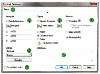
You define the block through the options in the Block Definition dialog box. You define items such as the name of the block, what objects will be in the block definition, the base point for the block, what units the geometry is drawn in, if it has to be scaled uniformly, whether it can be exploded, and a general description.
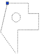
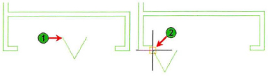
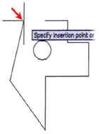
The base point you specify for the block defines the point you will use to position the block when inserting it in a drawing. This point also becomes the grip point for the block. The following illustration demonstrates the importance of selecting a proper base point. When creating a bi-fold door block and specifying the base point, you should snap to an object endpoint (1) so that when you insert the bi-fold door block in your drawing you can accurately place it at the end of the closet wall (2).
Command Access
Block Definition Dialog Box
For each block you create, you specify the name and the insertion base point; you also select the objects to include in your block definition. You can also choose among various other settings as needed.
Procedure: Creating a Block
The following steps give an overview of creating a block with the Block command.
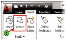
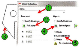
- On the ribbon, click Insert tab > Block panel > Create (1).
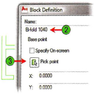
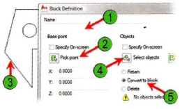
- In the Block Definition dialog box, enter a name for the block (2) and click Pick Point (3).
- Use an object snap to select a location on your object for the pick point.
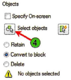
- Under Objects, click Select Objects (4).
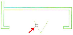
- Select the geometry to include in this block.
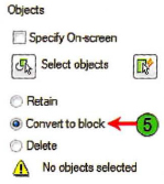
- Under Objects, select the option to define what happens to the selected geometry (5). Then click OK.
Note: Other options to enhance your block definitions include choosing whether the block is annotative or not, setting the block units, and giving the block a description.
Guidelines for Creating Blocks
- Name the blocks in a logical order, for example Door32, Door36, Window28, etc.
- Use the Purge command to purge unreferenced blocks that you will not be using in your drawing.
- Use the WBLOCK command to write the blocks in your drawing to individual drawing files. Type W to access the Write Block dialog box. Choose the block from your drawing and the Destination folder. Keep a folder for all of your block symbols to use in other drawings.
- You can nest blocks, meaning you can create a block that has other blocks within it. There is no limit to how many blocks can be nested in another block.
- If a block definition exists in a drawing and it is referencing a layer, you will not be able to delete the layer unless the block is purged.
- You cannot purge a reference if there is an instance of the block in the drawing.
- To make changes to a block, Explode it and re-create the block. If you re-create a block with the same name as a previously defined block, it will change all of the blocks in the drawing with that name.
- If you create a block and do not specify a Base point, the default base point will be 0,0,0.
- To Rename a block, use the Rename command. Select the old block name from the list and Rename it.
Practice Exercise | Create Blocks
In this practice exercise, you draw a simple object, create a block out of it, and name the block.
- Begin a blank drawing and create some simple geometry.
- To create a block:
- On the Insert tab, click Block panel > Create.
- In the Block Definition dialog box, for the block name, enter widget (1).
- For the block base point, click Pick Point (2).
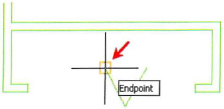
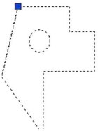
- Using object snap, select a point on the object (3).
- Click Select Objects (4) and select the geometry you have created. Press ENTER to return to the dialog box.
- Click the Convert to Block option (5).
- Select OK to exit the dialog box.
- To check that the geometry was converted to a block:
- With the command line blank, select the object.
- The object should be highlighted with one grip visible at the base point you selected for the block.
- Save this drawing to practice the Insert command in the next section.
Inserting Blocks
You use the Insert command to select a block definition or a file so you can place a block reference in your drawing. After selecting the block definition or file, you specify the insertion point, scale factor, and rotation angle for that block in the Insert dialog box or in the drawing window.
When you use Insert and select a file, a block definition of that entire file is added to the drawing database. So in a sense, the Insert command creates a block from a file on the fly.
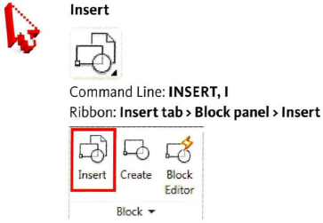
Command Access
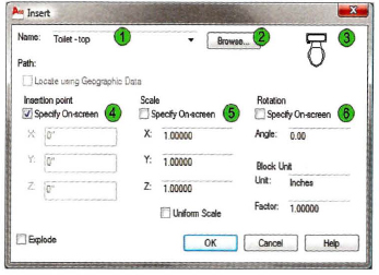
Insert Dialog Box
For each block you insert, you provide the block name, insertion point, scale, and rotation when you place the block in your drawing.
| Specify the name of a block to insert or the name of a file to insert as a block. | |
| Opens the select file dialog box allowing you to select a drawing file to insert as a block into your current drawing. | |
| Preview of the selected block when a preview image is available. | |
| Specify the insertion point of the block in your drawing. Decide whether the insertion point should be defined in the dialog box or on screen in the drawing area. If on screen, then select the Specify On-Screen option. If not, clear this option and enter the X, Y, and Z values. You will most often specify this point on screen. | |
| Specify the scale factor for the block. Decide whether the scale factor should be defined in the dialog box or on screen in the drawing area. If on screen, then select the Specify On-Screen option. If not, clear the option and enter the X, Y, and Z scaling factors. | |
| Specify the rotation angle of the block. Decide whether the rotation angle should be defined in the dialog box or on screen in the drawing area. If on screen, then select the Specify On-screen option. If not, clear the option and enter a rotation angle. You can also change this on screen while placing the block. |
Procedure: Inserting a Block
The following steps give an overview of inserting a block into a drawing.
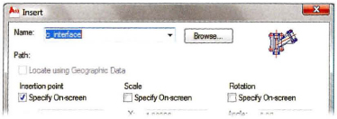
- On the ribbon, click Insert tab > Block panel > Insert.
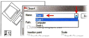
- In the Insert dialog box, select the block name from the list of blocks or click Browse and select a file.
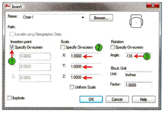
- Select the Specify On-Screen option (1), set your scale factor (2), and your rotation angle (3). The default rotation direction is CCW.
- Click OK.
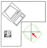
- Drag the block to the desired location and click to place it. You can use object snaps for an exact placement if desired.
Your block is placed in the drawing based on the parameters you specified.
Guidelines for Inserting Blocks
- When creating a Title block, you typically want the insertion point to be at 0,0. Otherwise, select the insertion point in the drawing.
- You can specify the X, Y scale and rotation angle at the command line when you insert the block if you uncheck Specify On-screen for Scale and Rotation.
- You can specify different X and Y scales. The block will be scaled proportionately.
- Browse to select a drawing file or a wblock that is located outside of the drawing.
- Once a drawing file is inserted into the current drawing, everything that the drawing geometry references will come with it such as blocks, layers, linetypes, text styles, and dimension styles.
- Use the Purge command to purge your drawing of unreferenced information that you will not need in your drawing. This will result in a more efficient drawing size.
- Once a block is inserted into a drawing you can move, copy, rotate, scale, mirror, or handle it like any other geometry.
- When you Explode a block, the geometry returns to its original properties.
- When you Explode a block that has another block nested in it, you can then Explode the nested block.
Practice Exercise | Inserting Blocks
In this practice exercise, you create and insert a block. You also draw a simple object then create a block out of it, called a widget. After you create the widget, you insert it into your drawing.
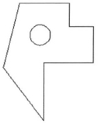
- Begin a blank drawing and create some simple geometry.
- To create a block:
- On the Insert tab, click Block panel > Create.
- In the Block Definition dialog box, for the block Name, enter widget (1).
- For the block base point, click Pick Point (2).
- Using object snap, select a point on the object (3).
- Click Select Objects (4) and select the geometry you have created. Press ENTER to return to the dialog box.
- Click the Convert to Block option (5).
- Select OK to exit the dialog box.
- To check that the geometry was converted to a block:
- With the command line blank, select the object.
- The object should be highlighted with one grip visible at the basepoint you selected for the block.
- To insert the block into the drawing:
- On the insert tab, click Block panel > Insert.
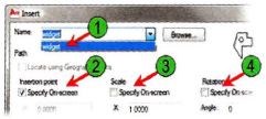
- Select the block name from the list (1).
- For the insertion point, place a check mark in the box next to the Specify on-screen option (2).
- Clear Scale (3). X, Y, and Z should be 1.000.
- Clear Rotation (4). The Rotation angle should be 0.
- Click OK.
- Specify the insertion point on the screen.
- On the Insert tab, click Block panel > Insert. Insert the block again, change the scale, and rotate the angle.