Lesson 47 | Creating Splines
This lesson describes how to create splines with the Spline command.
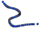
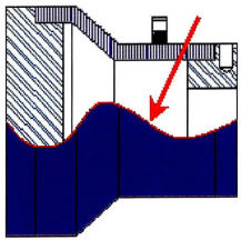
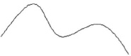
In many designs you need to show a smooth free-form line or edge that cannot be defined with straight lines and arcs, such as the curved edge shown here. Creating smooth curves with splines provides the look you want while creating an efficient object in the drawing file.
Objectives
After completing this lesson, you will be able to:
- Describe splines.
- Describe the procedure for creating a spline.
About Splines
Splines are smooth curves that pass through specified points. The curve elements of splines are not true arcs nor polylines, therefore splines must be handled differently from arcs or polylines with arc segments. The simplest way to modify the shape of a spline is to use its grips.
Spline Definition
Splines are curves which fit through control points using nonuniform rational B-splines (NURBS). Splines are specified in the drawing through fit points with a fit tolerance that permits a smooth curvature. Splines can be edited using grips or using the spline edit options. Polylines edited with the Spline option may resemble a spline, but will still be a polyline unless converted to a spline using the Spline edit object option. While a splined polyline can be converted to a spline, a spline cannot be converted to a polyline using basic AutoCAD commands.
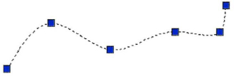
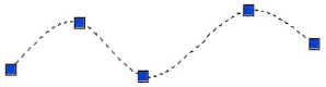
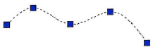
You create a spline similar to the way you draw a polyline, specifying each consecutive point or vertex to determine the shape of the object. Below is an example of a polyline. Each grip highlights a vertex point.

When creating a spline, a smooth curve is fit through the control points instead of line segments and the tangency of each endpoint must be specified. Below is an example of a spline passing through exactly the same points as the polyline shown above.
Spline Examples
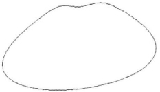
You can create a spline and close it using the spline edit command. Below is an example of a closed spline.
You can create a polyline and use the polyline edit command to create a splined polyline. Then you can convert it to a spline using the spline edit command with the Object option. Both a splined polyline and a splined polyline converted to a spline would appear identical, as shown below, however both would behave differently because they are inherently different objects. It is the tangency of the endpoints and the tolerances of the control points that keep the curvature smooth and makes a spline behave a particular way.

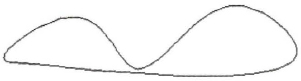
The following example shows the same polyline object splined, converted to a spline object, and closed using the spline edit command. This object is a closed spline.
A polyline splined using the Polyline edit option and closed produces a different result. The object below is a closed polyline.
![]()
All of the objects in these examples were created using exactly the same control points. One was created using the spline command the other was created using the polyline command.
Creating Splines
Using the Spline command, you create smooth curves that pass through or near the points you specify. The spline passes through the points by default because the initial tolerance value for the spline is zero.
Each spline is a single object in the drawing with all of the defining points, tolerances, and tangencies stored as part of that spline. The software creates these smooth splines based on nonuniform rational B-spline (NURBS) curves.
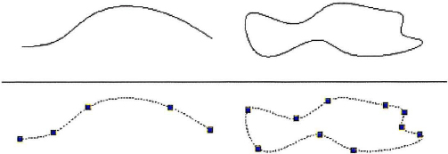
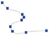
The following image shows two spline objects. The lower half of the image shows the points that define the spline.
Command Access
Command Access
Spline Key Terms
- Open Spline: A spline in which the first and last points are not joined together to create a single continuous flowing spline.
- Closed Spline: A spline that has the same first and last point and was created with the Close option of the Spline command.
- Fit Points: The points in the drawing that you specify when you create the spline.
- Control Points:
Note: After you refine a spline through its control points, the fit point data is lost.
- Fit Point Tolerance: A maximum value in drawing units for how closely you must draw the spline to the fit points you specify. The default value of zero means that the spline must be drawn directly through the fit point.
- Start or End Tangencies: For open splines, you can define a vector direction through the first or last fit point to which the spline must be tangent. For closed splines, the tangency controls the transition between the first and last defined segments.
Procedure: Creating a Spline
The following steps give an overview of creating a spline in a drawing.
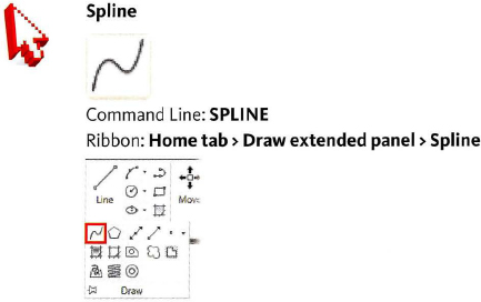
- On the ribbon, click Home tab > Draw panel > Spline.
- Click in consecutive order the locations that the spline must be drawn through.
- Right-click. Click Enter.
- Do one of the following:
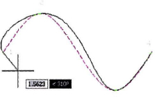
- Right-click to accept the default tangency through the first point.
- Move the cursor to define a direction to which the first part of the spline must be tangent. Click. The dashed magenta spline shows the path if you accept the default tangency.
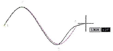
- Do one of the following:
- Right-click to accept the default tangency through the last point.
- Move the cursor to define a direction to which the last part of the spline must be tangent. Click. The dashed magenta spline shows the path if you accept the default tangencies.
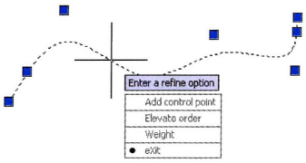
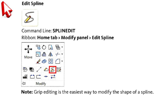
Procedure: Editing a Spline
The following steps give an overview of editing a spline in a drawing using grips.
- With the Command line blank, select the spline.
- Select a grip control point (1) and drag it to a new location (2) and click.
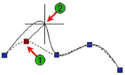
- When finished adjusting the spline using grips, press ESC.
Procedure: Convert Spline to Polyline
The following steps give an overview of converting a spline into a polyline.
- With the command line blank, select the spline.
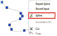
- Right-click in an open area of the drawing and click Spline.
- If Dynamic Input is turned off, right-click in an open area of the drawing and click Convert to Polyline. If Dynamic Input is turned on, the menu automatically appears.

- On the command line, enter a precision value or press ENTER to accept the default value. The spline is converted to a polyline.
- Select the polyline to view or edit it.