Lesson 05 | Creating Basic Objects
All drawings consist of basic objects that you create using basic commands. In this lesson, you learn how to create objects such as lines, circles, arcs, rectangles, and polygons. You also learn how to use the Erase command to erase objects.
Learning to create basic geometry is critical to success in the software. As you become proficient with basic geometry creation, you can move on to creating more advanced object types.
Objectives
After completing this lesson, you will be able to:
- Use the Line command to create lines in the drawing.
- Use the Circle command to create circles in the drawing.
- Use the Arc command to create arcs in the drawing.
- Use the Erase command to erase objects in the drawing.
- Use the Undo and Redo commands to return to previous drawing states.
- Use the Rectangle command to create rectangles in the drawing.
- Use the Polygon command to create equal-sided polygons in the drawing.
Line Command
Use the Line command to create a single line or multiple line segments from a start point to an endpoint.
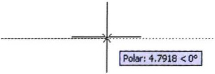
The following illustration shows a line segment being drawn using the dynamic input interface to specify the length (1) and angle (2) of the segment.
Command Access

Command Options
The following Line command options are available from the shortcut menu (right-click) or the command line:
| Option | Absolute |
| First Point | (default) Specifies the start point of the line segment. |
| Next Point | (default) Specifies the endpoint of the line segment. Continue to specify next points for additional line segments. |
| Undo | Removes the previous line segment without exiting the Line command. Select or enter the capitalized letter only. |
| Close | Appears only after you have drawn two line segments. Uses the first point of the line segments as the next point for the current segment to create a closed boundary of line segments. Select or enter the capitalized letter only. |
Line Command Guidelines
- Use to create a single line or multiple line segments.
- Use the Close option to connect the last segment to the beginning of the first segment.
- Line segments, even though connected, are separate, independent objects.
- If you begin the Line command and press ENTER instead of selecting a start point, the Line will resume at the last point selected, such as the end of the previous line.
- You can Undo a line segment without completely exiting the line command by entering U and then pressing ENTER, or selecting Undo.
Practice Exercise | Line Command
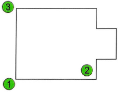
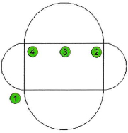
In this practice exercise you will practice using the Line command to draw the object below.
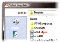
- Begin a new drawing.
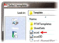
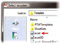
- In the Select template dialog box, select the acad template file (.dwt) and click Open.
- Be sure the following status bar settings are on:
- Polar tracking
- Object snap
- Object snap tracking
- To draw the horizontal line:
- On the ribbon, click Home tab > Draw panel > Line.
- For the start point (1), select a point on the screen.
- Drag the line to the right until you see that the tooltip indicates the polar angle is 0.
- Enter 4 and press ENTER.
- Continue with the Line command to draw the remaining line segments from points (2) to (3):
- Drag your mouse up until you see that the tooltip indicates that the Polar angle is 90.
- Enter 1 and press ENTER.
- Drag to < 0, and enter 1 and press ENTER.
- Drag to < 90, and enter 1.5 and press ENTER.
- Drag to < 180, and enter 1 and press ENTER.
- Drag to < 90, and enter 1 and press ENTER.
- Drag to < 180, and enter 4 and press ENTER.
- Drag the mouse down to Polar < 270 until you see that the object snap indicates you have reached the original endpoint (1), and click the endpoint. Be sure to click inside the Endpoint Object Snap box. Press ENTER to end the Line command.
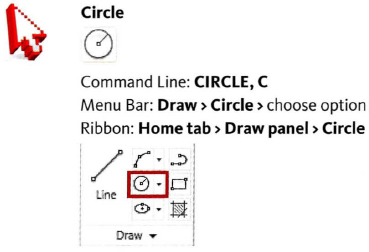
Circle Command
Use the Circle command to create circles in the drawing. When you start the Circle command, you are prompted to select a center point, then specify the radius. Use the data input methods discussed earlier to input these values.
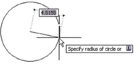
In the following image, the circle center point is selected and you are prompted to specify a radius.
Command Access
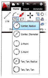
Circle Command Options
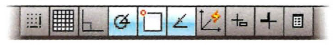
Circle options can be accessed from the drop-down menu next to the Circle button.
Circle options can be selected from the shortcut menu (right-click) or entered at the command line. Enter the capitalized letter(s) only.
| Option | Description |
| Specify center point | (default) Click a point or enter a coordinate for the center of the circle. |
| D | After you specify a center point, you have the option to specify a Diameter instead of the radius. |
| 3P | Create the circle based on three points you specify to define the circle's diameter. |
| 2P | Create the circle based on two points you specify to define the circle's diameter. |
| Ttr (tan tan radius) | Create a circle tangent to other objects at a radius you specify. |
Tip
The Circle command remembers the radius or diameter of the last circle drawn. If the prompt for the radius or diameter contains a value in brackets, press ENTER to reuse the value for the radius or diameter of the new circle. Specify radius of circle or [Diameter] <25.000>: Press ENTER to create a new circle with a 25 unit radius.

Circle Command Guidelines
- The Circle default when executed from the command line is Center, Radius. Specify a center point and a radius to define the circle.
- When you specify a Circle option from the drop-down menu, that button remains visible in the toolbar panel.
- After specifying a center point for the Circle, simply press ENTER, if you want the circle to be the same size as the last circle made.
- After specifying a center point, enter D and press ENTER if you prefer to enter a diameter for the circle.
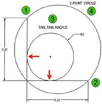
Practice Exercise | Circle Command
In this practice exercise, you use the Tan, Tan, Radius, Circle command and the 2-Point Circle. First, you draw two adjacent lines that are 5.25 units each.
- Begin a new drawing.
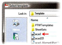
- In the Select template dialog box, select the acad.dwt template file and click Open.
- Be sure the following status bar settings are on:
- Polar tracking
- Object snap
- Object snap tracking
- To draw the lines:
- Start the Line command.
- For the start point, select the endpoint of the line (1).
- Drag the mouse down until the Polar angle indicates that it is < 270. Enter 5.25 and press ENTER.
- Drag the mouse to the right until the Polar angle indicates < 0. Enter 5.25 and press ENTER.
- Press ENTER to end the Line command.
- Adjust the display of your drawing using Zoom or Pan Real-time, if necessary.
- To draw the smaller circle (3):
- On the ribbon, click Home tab > Draw panel > Circle drop-down > Tan, Tan, Radius.
- Move the cursor to the vertical line until you see the Deferred Tangent object snap and then click.
- Now move the cursor to the horizontal line until you see Deferred Tangent again and click.
- Specify the radius of the circle. Enter 2 and press ENTER.
- To draw the larger circle (4):
- On the Home tab, click Draw panel > Circle drop-down > 2-Point.
- Move the cursor to the end of the vertical line (1) until you see the Endpoint object snap and click.
- Now move the cursor to the end of the horizontal line (2) until you see the Endpoint object snap and click.
Arc Command
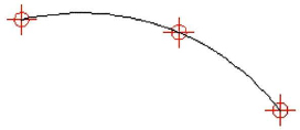
The Arc command creates an arc based on three points. Using the default method for creating an arc, you specify a start point, a second point, and an end point. The arc radius and center point are calculated based on the position of the three consecutive points you specify.
The following illustration represents an arc being created through three points.
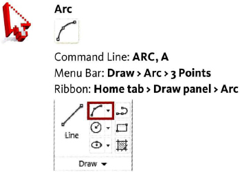
Command Access
Command Options
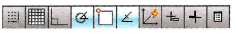
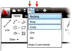
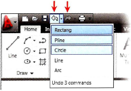
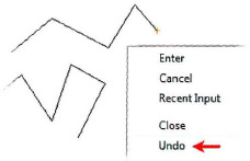
Arc options can be accessed from the drop-down menu next to the Arc button. The most common Arc options are indicated by red arrows in the following illustration.
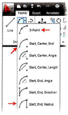
Arc options can be selected from the shortcut menu (right-click) or entered at the command line. Enter the capitalized letter(s) only and follow the command line prompts the capitalized letter(s) only.
| Option | Description |
| C | Specify the center point of the arc. Then you will be prompted to specify the start point of the circle. |
| Angle | Specify included angle. |
| Length | Specify the length of the angle chord. |
Arc Note
Arcs are drawn in a counterclockwise direction unless using the 3-Point default method.
![]()
Practice Exercise | Arc Command
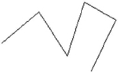
In this practice exercise, you use the Start, Center, End Arc command. First, you draw a rectangle. Remember that arcs are drawn counterclockwise, so it is important that you select your points in the correct order. Draw all of the arcs so that they are outside of the rectangle.
- Begin a new drawing.
- In the Select template dialog box, select the acad.dwt template file and click Open.
- Be sure the following status bar settings are on:
- Polar tracking
- Object snap
- Object snap tracking
- To draw the rectangle (any size):
- On the ribbon, click Home tab > Draw panel > Line.
- For the start point, specify the first corner (1).
- Use Polar Tracking to create a rectangle and make sure you snap to the first corner (1) when done.
- To draw the first arc:
- On the ribbon, click Home tab > Draw panel > Start, Center, End Arc (select the down arrow by the Arc button).
- Specify the start point of the arc. Click the rectangle Endpoint (2).
- Specify the center point of the arc. Enter MID and press ENTER.
- Click the midpoint of the rectangle at (3).
- Specify the endpoint of the arc. Click the rectangle endpoint (4).
- Repeat these steps until you have finished. Remember to draw your arcs in a counterclockwise direction, using the Start, Center, End Arc command.
Erase Command
Use the Erase command to remove geometry from the drawing. You can select objects by picking them directly, or using selection options such as a window or crossing window.
Command Access

OOPS Command
Use the OOPS command to retrieve geometry you accidentally erased without undoing any work you did since you last Erased.
![]()
Use a Shortcut Menu
Use the shortcut menu to alter your design more quickly. Select the objects you want to erase before entering the command or right-click and select Erase from the shortcut menu.

Practice Exercise | Erase Command
Practice the Erase command. First, draw some lines, circles, and arcs. Then practice removing them from your drawing. Try a few different ways to select the objects.
- Begin a New drawing.
- In the Select Template dialog box, select the acad.dwt template file and click Open.
- Draw at least eight objects in the drawing window:
- Start the Line command. Draw some lines.
- Start the Circle command. Draw some circles.
- Start the Arc command. Draw some arcs.
- To Erase, try these methods:
- On the ribbon, click Home tab > Modify panel > Erase. Select three objects to erase, then press ENTER.
- On the command line, enter U. Press ENTER to undo.
- With the command line blank, select three objects. Notice the objects are highlighted and the grips are visible. Right-click and select Erase from the shortcut menu.
- On the command line, enter U. Press ENTER to undo.
- Start the Erase command. At the Select objects prompt, enter L (for Last) and press ENTER. Notice that the last object you drew is highlighted. Press ENTER to start the Erase command.
- With the command line blank, select an object. Press DELETE.
- Erase the objects using the Cross window option.
- Enter E on the command line and press ENTER. At the select objects prompt, select a spot in the blank area on the right side of the drawing. This will initiate a selection window. Drag your mouse up (or down) and to the left. Notice that the selection window is made of dashed lines.
- Cross the objects in the drawing, but leave some parts of the objects out of the selection window. Select to specify the opposite corner of the selection window.
- Notice that the objects that were completely inside the selection window are highlighted as well as the objects that were crossed by the selection window. Press ENTER to erase the objects.
- Enter U at the command line and press ENTER to undo.
- Erase the objects using the Window option.
- On the command line, enter E. Press ENTER. At the select objects prompt, click in a blank area on the left side of the drawing. This will initiate a selection window. Drag your mouse up (or down) and to the right. Notice that the selection window is made of a continuous line.
- Cross the objects in the drawing, so that some are completely within the selection but others are partially out of the window. Click to specify the opposite corner of the selection window.
- Notice that the objects that were completely inside the selection window are highlighted but the objects that were partially out of the selection window are not highlighted. Press ENTER to erase the objects.
- On the command line, enter U. Press ENTER to undo.
- To use the OOPS command on previously erased objects:
- On the command line enter, E. Press ENTER. Enter ALL at the Select objects prompt and press ENTER.
- Press ENTER again to start the Erase command.
- Now draw some more objects using the Line, Circle, or Arc commands.
- Enter OOPS and press ENTER.
- Notice that the objects you erased were returned to the drawing.
- Close all drawings. Do not save.
Undo and Redo Commands
Use the Undo command to step back through every action you made, including pan and zoom. Use the Redo command to step forward through those actions again. These commands are conveniently located on the Quick Access toolbar. You can Undo at any point in the drawing session, even within some of the draw and modify commands. However you can only Redo immediately after an Undo command.
You may also type the Undo command at the command line. Enter U and press ENTER. If you continue to press ENTER, the Undo command will be repeated. If you enter the entire word UNDO at the command line and press ENTER, you will see a list of Undo options at the command line prompt.
If you are working in the AutoCAD Classic workspace the Undo and Redo buttons include down arrows that reveal lists which you can choose to undo or redo up to a selected item or step.
Command Access
Command Access
Command Options
The following options are available only when you enter the entire word UNDO at the command line. Right-click to access the shortcut menu or enter the capitalized letter of the option.
| Option | Description |
| Auto | Groups all actions of a single command, making them reversible with a single U command. |
| Control | Limits or turns off Undo. |
| Begin, End | Groups a sequence of actions into a set. After you use the Begin option, all subsequent actions become part of this set until you use the End option. |
| Mark | Places a mark in the undo information. If you use the Back option, all sequences are undone to the mark. |
| Back | Undoes all work to the first mark that is encountered. If there are no marks placed in the undo information, the following prompt appears:
This will undo everything. OK? <Y> If you continue, all steps in the drawing are undone to the beginning of the drawing session. |
Note
The Mredo command is similar to the expanded Undo command in that it offers other options to redo, such as the last step of all of the prior Undo operations.
![]()
Procedure: Using Undo and Redo
The following steps give an overview of how to use the Undo and Redo commands in the drawing.
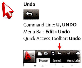
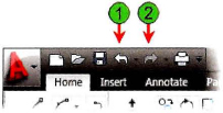
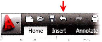
- On the Quick Access Toolbar, click Undo (1), or enter U in the command line.
- Each time you click Undo a single operation is undone. If you entered U in the command line, you can continue to press ENTER to repeat the Undo command.
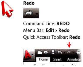
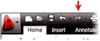
- To Redo an operation, click Redo (2) in the Quick Access toolbar or enter REDO immediately following an undo operation.
- Continue to click Redo until the drawing is returned to the desired state.
- You can access the Undo or Redo lists on the Standard Toolbar to highlight the steps to undo or redo.
Undo and Redo Guidelines
- Undo information is only saved in the current session of the drawing. If you exit the drawing and reopen it, you cannot undo steps that were done in the previous session.
- The Redo command is only available immediately after an Undo operation.
- You can undo all the way back to the beginning of the drawing.
- Enter UNDO on the command line to view advanced Undo options.
- Enter MREDO on the command line to view advanced Redo options.
- If you have multiple drawings open at once, each drawing contains separate undo information and, as a result, you can use the Undo command independently within each drawing.
Practice Exercise | Undo and Redo Commands
Most of the time you use Undo and Redo in single steps. In this exercise, you practice using the Undo and Redo commands and some of the Undo options.
- Begin a new, blank drawing.
- In the Select Template dialog box, choose the acad.dwt template.
- Draw some circles and then undo them:
- On the command line, enter C. Press ENTER. Draw five circles.

- On the Quick Access toolbar, click Undo until all five circles are gone.
- On the Quick Access toolbar, click Redo repeatedly to bring all five circles back.
- Draw some lines. Practice using the Undo command within the line command.
- On the command line, enter L and press ENTER. Draw several continuous line segments. Press ENTER to complete the Line command.
- On the command line, enter U. Press ENTER. Notice that all of the line segments are undone.
- On the command line, enter L. Press ENTER. Draw several continuous line segments. Do not exit the line command. Right-click and select Undo from the shortcut menu.
- Notice that the last line segment is undone. Right-click and select Undo again from the shortcut menu. Do not exit the line command. Continue to draw line segments. Press ENTER to complete the Line command.
- Practice using the Undo options, BEgin and Back.
- On the command line, enter UNDO. Press ENTER.
- Enter BE (for BEgin). Press ENTER.
- On the command line, enter L. Press ENTER. Draw some continuous line segments. Press ENTER to complete the line command.
- Draw some circles, rectangles and arcs.
- With the command line blank, press the up arrow on the keyboard to scroll to the UNDO command. If you pass it, use the down arrow to scroll back. When Undo is in the command line, press ENTER.
- Enter B (for Back). Press ENTER.
- This should undo the lines that you created.
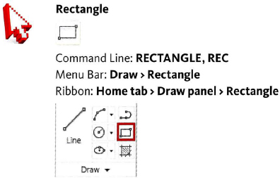
Rectangle Command
Use the Rectangle command to create rectangular objects. A single polyline object is created with this command. The simplest method for creating a rectangle is to specify the first corner, then the opposite corner. Other options for creating the rectangle include the Area, Dimension, and Rotation options.
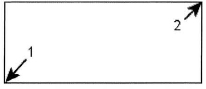
This illustration shows a rectangle with the point used to create it specified.
Command Access
Command Options
These Rectangle options are available after you have selected the first point for the rectangle. Right-click to select from the shortcut menu or enter the capitalized letter at the command line.
| Option | Description |
| Area | Use this option to create a rectangle based on its area and the distance of one side, whether length or width. |
| Dimensions | Use this option to manually enter the length and width of the rectangle. |
| Rotation | Use this option to specify a rotation angle for the rectangle. |
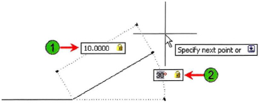
When you use the Distance or Area options to specify the rectangle size, the Length prompt refers to the horizontal distance, while the Width prompt refers to the vertical distance. If the rectangle is being rotated, Length refers to the distance along the rotation angle, while Width refers to the distance perpendicular to the rotation angle.
Rectangle Command Guidelines
- The Rectangle command generates polyline objects.
- Because rectangles are polylines, selecting any segment selects the entire rectangle.
- The simplest method for drawing a rectangle is to specify the first corner, then the opposite corner using relative XY coordinates. Example: after selecting the fist point, enter @4,5 to make a rectangle that is 4 × 5.
- Rectangles can be initiated from any corner. After selecting the first point, if you enter @-4, -5 you will make a rectangle that is located below and to the left of the first point selected.
Note
When using the dimension input option, you need to click to select an orientation. After you enter the length and width values, move your cursor up and down or left and right to view the available orientations. When the orientation you want is displayed, click to create the rectangle.
![]()
Practice Exercise | Rectangle Commands
Practice drawing rectangles using coordinate dimensions. Practice other Rectangle options. Adjust your display as you work using the Zoom and Pan Realtime commands.
- Open a new drawing.
- Check that the Dynamic Input option on the status bar is not selected.
- To draw Rectangles using relative coordinates @x, y:
- On the ribbon, click Home tab > Draw panel > Rectangle.
- To specify the first corner, click anywhere in the drawing window.
- At Specify first corner point prompt, enter @4,5 and press ENTER.
- Notice that a rectangle was drawn up and to the right of the first point selected. If this did not happen, then you forgot to enter @ before the x, y coordinates. Try again.
- Continue to draw Rectangles using relative coordinates @x, y:
- On the Home tab, click Draw panel > Rectangle. Click the first corner anywhere in the drawing window.
- Enter the relative coordinates @x, y and press ENTER to make rectangles with the following dimensions:
- 6 × 7 (enter @6,7)
- 7 × 6 (enter @7,6)
- 9 × 9 (enter @9,9)
- Turn on the Dynamic Input option on the status bar.
- To draw a rectangle 7 × 10:
- On the Home tab, click Draw panel > Rectangle. Click the first corner anywhere in the drawing window.
- Enter 7,10 (do not enter the @ symbol) and press ENTER.
- A rectangle should have been made up and to the right of the start point. If not, check to be sure that Dynamic Input is on in the Status Bar and try again.
- Press F2.
- Observe that @ symbol was automatically added to the coordinate making it relative to the last point you selected.
- Practice making the following rectangles:
- 2 × 2 (enter 2,2)
- 4 × 6 (enter 4,6)
- To use the Rectangle > Area option:
- On the Home tab, click Draw panel > Rectangle.
- Click a point anywhere in the drawing window for the first corner.
- Enter A (for Area) and press ENTER.
- Enter 35 for the area and press ENTER.
- To specify the Length, press ENTER to accept the default if [Length] is already in brackets. Otherwise, enter L and press ENTER.
- Enter 7 for the rectangle length and press ENTER.
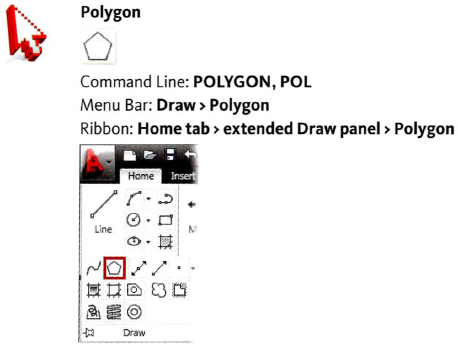
Polygon Command
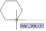
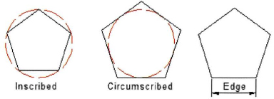
Use the Polygon command to create regular polygon geometry by specifying the center point and radius of an imaginary circle, or the start point and endpoint of one of the polygon edges. Regardless of the method you choose to define the polygon, all of its sides are equal in length.
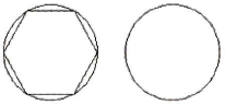
The default method for creating polygons is to specify a center point and radius. When you choose this method, you must choose either the Inscribed or Circumscribed option. Depending on the option you choose, the size of the polygon is calculated as shown in the following image.
Command Access
Command Options
The following Polygon command options are available from the shortcut menu (right-click) or the command line. Enter the capitalized letter(s) of the option.
| Option | Description |
| Enter number of sides | Polygons can have between 3 and 1024 sides. |
| Specify center of polygon | (default) Note that while you may pick any point for the center of a polygon, once it is made you will not be able to simply snap to its center. |
| Inscribe in circle | Draws a polygon within a designated radius. |
| Circumscribed about circle | Draws a polygon outside of a designated radius. |
| Edge | Draws a polygon based on the number of sides and the length of a specified edge. |
Polygon Command Guidelines
- Polygons can have between 3 and 1024 sides.
- Regardless of the number of sides you choose, all sides are equal in length.
- The Polygon command creates polyline objects.
- Polygon is a good tool for creating balloons and other types of annotation symbols.
Practice Exercise | Polygon Commands
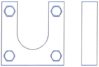
Use the Polygon command to draw a 6-sided polygon that is inscribed about a circle, one that circumscribed about a circle, and one that has an edge length of 1. First, draw two circles with radius of 1.5, then draw the polygons.
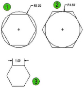
Note: Although you will draw the inscribed and circumscribed polygons inside a circle, it is only to compare the two options. It is not necessary to draw a circle first to make a polygon.
- Open a new drawing using the acad.dwt template.
- Click the following status bar options so that they are on:
- Polar tracking
- Object snap
- Object snap tracking
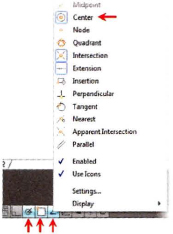
On the status bar, right-click Object Snap and click the Center snap mode so that it is also on.
- To draw a polygon that is inscribed in a circle, as shown in example 1:
- On the ribbon, click Home tab > Draw panel > Polygon.
- Enter 6 for the number of polygon sides.
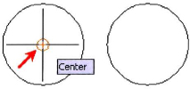
- Click the center of the circle for the center of the polygon. If object snap is on and center mode is selected, you will see the center snap indicator, as shown below.
- Enter I (for Inscribed). Press ENTER.
- To specify the radius of the polygon circle, enter 1.5. Press ENTER.
- To draw a polygon that is circumscribed about a circle, as shown in example 2:
- On the Home tab, click Draw panel > Polygon.
- Enter 6 for the number of polygon sides.
- Click the center of the circle for the center of the polygon. Click when you see the circle's center object snap.
- Enter C (for Circumscribed). Press ENTER.
- To specify the radius of the circle, enter 1.5. Press ENTER.
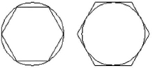
- To draw a polygon using the Edge option, as shown in example 3:
- On the Home tab, click Draw panel > Polygon.
- Enter 6 for the number of polygon sides.
- Enter E (for Edge). Press ENTER.
- Click anywhere in the drawing window to specify the first endpoint of the edge.
- Drag the cursor and notice that with PolarSnap on you can specify the polar angle the edge. Enter 1. Press ENTER.