Lesson 46 | Working with Polylines
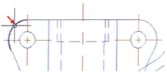
This lesson describes how to create and edit polylines. The following illustration shows polyline segments in a lot boundary line and an arrow created with a polyline.
With polylines you can create geometry and return information much more quickly than with other methods. When you use polylines, you can easily calculate a perimeter distance or the area of an irregular shape. By offsetting polylines, you do not spend time trimming or extending geometry at the corners. Sharp corners are maintained in the offset.
Objectives
After completing this lesson, you will be able to:
- Describe polylines and how they differ from standard objects.
- Use the Polyline command to create polylines.
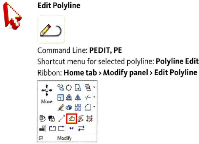
- Use the Edit Polyline command to edit polylines.
About Polylines
Polylines enable you to create more complex geometry while at the same time, in some cases, simplifying the creation process. Object selection is also simplified because several objects can be combined into a single editable object.
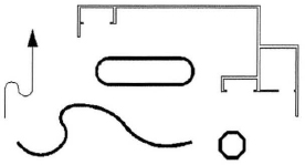
In the following illustration, several objects are shown and each of them represents a single polyline that was created using different methods.
Definition of Polylines
Polylines are special types of entities that incorporate segments of common entities such as lines and arcs into a single object. Polylines also have special properties that are not available on other objects. These properties include:
- Global Width Start
- Segment Width End
- Segment Width
In addition to the properties mentioned above, polylines also provide significantly more choices for controlling their shape during object creation as well as specific tools and options for editing the objects after you create them.
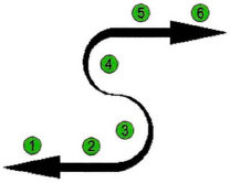
In the following illustration, a polyline containing 6 segments is shown. Segments (1) and (6) have varying start segment widths and end segment widths. Segments (2) and (5) are constant widths segments. Segments (3) and (4) are varying width arc segments.
Example of Polylines Being Used in a Drawing
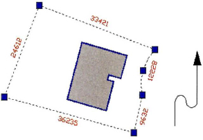
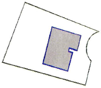
In the following illustration, polylines are used to represent the lot boundary and proposed building footprint. Using the polyline objects enables the designer to quickly determine properties such as area or perimeter and also to add a global width to emphasize the polylines.
Creating Polylines
You use the Polyline command to create line and arc segments as a continuous single object. Each segment of a polyline is connected at its endpoint to the next segment in the object. When creating polylines, you can switch back and forth between straight line segments and arc segments. You can also set a single width for all segments of the polyline, or you can vary the width of a segment from its beginning to its end.
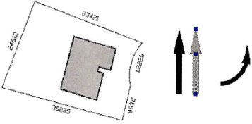
The following illustration shows examples of polylines. You can calculate the area of the lot with the Area command when the boundary is one object. The footprint of the structure stands out in the design when you add width to its polyline outline. You can create straight and arcing arrows from two segments of a polyline by varying the width of the arrowhead segment from beginning to end.
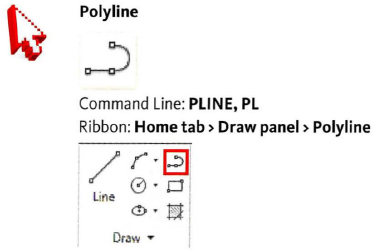
Command Access
Command Options
These command options are for creating or changing polylines.
| Option | Description |
| Arc | Use this option to draw arc segments within the polyline. |
| Close | Use this option to automatically create an arc or line segment from the last point entered to the first point of the polyline. |
| Undo | Use this option to remove the previous segment when you want to either exclude it or create a new segment with a different appearance. |
| Width | Use this option to set the width of a polyline in drawing units from the first vertex to the second vertex. |
| Line | Use this option to resume drawing straight line segments within the polyline after creating arc segments. |
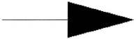
Procedure: Creating a Custom Arrowhead
The following is an overview of creating a custom arrowhead using the Pline command.
- On the ribbon, click Home tab > Draw panel < Polyline.
- Pick your start point.
- Drag your cursor to the right at 0 degrees. Enter the length of the arrow.
- Right-click. Click Width.
- Enter the starting width which should be larger then the ending width.
- Enter the ending width which is usually 0.
- Drag your cursor to the right at 0 degrees. Enter a value or click a point to define the length of the arrowhead.
- Press ENTER.
Editing Polylines
You modify polylines using the same commands you use to modify a line or circle. Commands like Copy, Erase, Move, Offset, and Array can all be used to modify a polyline. When you use the Fillet or Chamfer command and at least one of the segments you select is a polyline, the other selected segments become part of the polyline object. However, you cannot fillet or chamfer the first segment of a polyline with the last segment of the same polyline. To create a fillet or chamfer in that situation, you must first use the Explode command to break the polyline into individual line and arc objects.
Polyline Edit
You use the Pedit command to change certain characteristics of a polyline or to convert a line or arc into a polyline.
Command Access
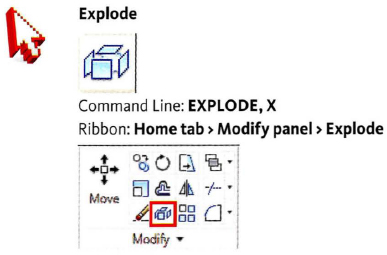
Exploding Polylines
You use the Explode command to convert a polyline into its most basic shapes such as lines and arcs. When you explode a polyline, all the attributes associated with polylines, such as width, are lost and a separate object is created for each segment of the polyline.
Command Access
Procedure: Joining Lines and Arcs into a Polyline
The following is an overview of using the Join option of the Pedit command to combine a series of lines and arcs into a single polyline.
- On the ribbon, click Home tab > Modify panel > Edit Polyline.
- Select any one of the lines or arcs that you are going to join into a polyline.
- If the selected object is already a polyline, you will not be prompted for this step. If the selected object is not a polyline, press ENTER at the prompt asking you to make it one.
- Click Join.
- Select all the objects that you want to join into a polyline. Press ENTER.
Note: Use a window or crossing selection for the best results. It does not matter if extra objects are selected.
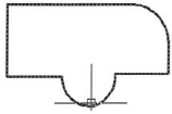
- Press ENTER to complete the polyline edit. The object now highlights as a single object when selected as shown in the following image.
Procedure: Exploding a Polyline
The following is an overview of using the Explode command to break a polyline into individual lines and arcs.
- On the ribbon, click Home tab > Modify panel > Explode.
- Select one or more polylines in your drawing.
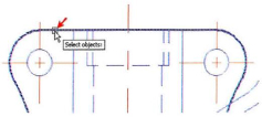
- Press ENTER to complete the explode. Your profile highlights as individual objects as shown in the following image.