
Challenge Exercise | Mechanical
In this exercise, you use what you learned about creating drawing objects to represent an edge on a part, create a border around a view, and create a closed loop to calculate area. You will also update your layout including a titleblock.
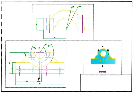
The completed exercise
Completing the Exercise
To complete the exercise, follow the steps in this book or in the onscreen exercise. In the onscreen list of chapters and exercises, click Chapter 11: Creating Additional Drawing Objects. Click Challenge Exercise: Mechanical.
![]()
- Open the drawing you saved from the previous challenge exercise, or open M_MECH-Challenge-CHP11.dwg.
- In the side views for both the base part and assembly, the cut for the hole is too high with an arc. Draw the representation correctly using an ellipse.

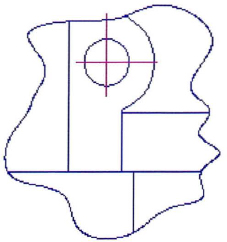
- Change the border around the detail view from a circle to a spline shape.
- Calculate the square millimeter area of the two flat surfaces in the front view of the base part.
(Value Check: The area of the lower face = 17185.9487)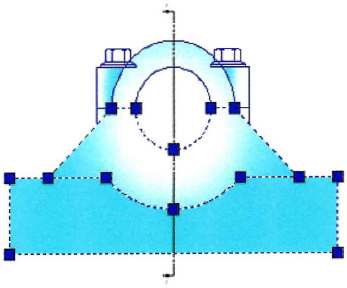
- Update the Parts layout.
- Switch to the Parts layout.
- Insert the Titleblock block.
- Save and close the drawing.
Chapter Summary
To meet your design needs, you can create multiple segments of lines and arcs as a single polyline, you can create smooth curved geometry as splines or ellipses, and you can add tables to your drawings.
Having completed this chapter, you can:
..................Content has been hidden....................
You can't read the all page of ebook, please click here login for view all page.