Lesson 29 | Creating an Angled Corner Between Two Objects
This lesson describes how to use the Chamfer command to create chamfer features on objects in the drawing.
There are many situations that call for a chamfer. Any time you need to create an angled intersection on objects in the drawing, the Chamfer command should be your first choice.
After completing this lesson, you will be able to identify options of the Chamfer command and use the command to create chamfered features.
Objectives
After completing this lesson, you will be able to:
- Use the Chamfer command to create chamfer features.
Creating Chamfers
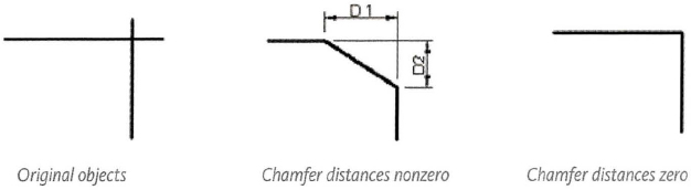
You use the Chamfer command to quickly create a line between two nonparallel lines. It is usually used to represent a beveled edge on a corner. You can chamfer lines, polylines, xlines, and rays.
Command Access
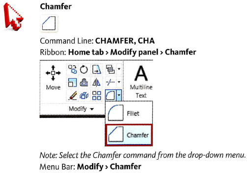
Command Options
The following options are available when using the Chamfer command.
| Option | Description |
| Undo | Use this option to undo the previous action of the Chamfer command. |
| Polyline | Use this option to chamfer a 2D polyline. All polyline vertices are chamfered at the current distance or angle settings. |
| Distance | Use this option to specify distance values for the chamfer. |
| Angle | Use this option to create the chamfers based on one distance and an angle. |
| Trim | Use this option to set the Trim and No Trim modes. When Trim mode is active, the objects being chamfered are trimmed to the start of the chamfer lines. When No Trim mode is set, the objects selected for the chamfer are not trimmed. |
| Method | Use this option to switch between the Distance or Angle methods for creating the chamfer. |
| Multiple | Use this option to create multiple chamfers without having to restart the command. |
Using Chamfer Options
- With the Distance method, you specify the amount that each line should be trimmed or extended.
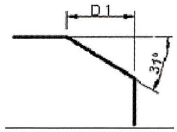
- With the Angle method, you can also specify the length of the chamfer and the angle it forms with the first line.
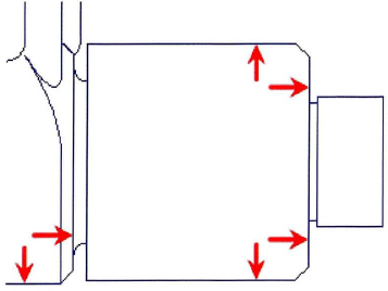
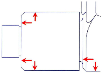
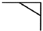
- Using the Trim and No Trim modes, you can trim or extend chamfered objects to the chamfer line or retain the chamfered objects as they were before the chamfer, as shown next.
- You can chamfer all corners of a polyline using the Polyline option.
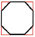
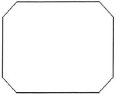
- The Multiple option allows you to chamfer more than one set of objects without leaving the command. For example, you could chamfer the four corners of the square shown next with one Chamfer command.
Procedure: Creating Chamfers
The following steps give an overview of creating chamfers with the Chamfer command.
- Start the Chamfer command.
- Confirm the settings on the command line. If necessary, adjust the options as required for the design intent.
Command: _chamfer(NOTRIM mode) Current chamfer Dist1 = 1.0000, Dist2 = 1.5000 Select first line or [Undo/Polyline/Distance/Angle/Trim/mEthod/Multiple]:
- Select the first object to be chamfered.
- Select the second object to be chamfered. The chamfer feature is created.
Note: If you choose the Polyline option, step 4 is not required, as all vertices of the polyline will be filleted at once.
Chamfer Guidelines
- If both objects being chamfered are on the same layer, the chamfer line is created on that layer. Otherwise, the chamfer line is created on the current layer.
- Entering chamfer distances of o creates a sharp corner.
- Setting equal chamfer distances is the same as setting the angle at 45 degrees.
- When setting chamfer distances the first distance is always applied to the first line you pick.
- Chamfering a line to a polyline will automatically join it to the polyline.
- A closed polyline will chamfer in a counter-clockwise direction.
- Hold down SHIFT while selecting the object to override the chamfer distance values and create a sharp corner.
Practice Exercise | Creating Chamfers
In this practice exercise, you draw an 8 × 6 rectangle and create chamfers using the Chamfer command.
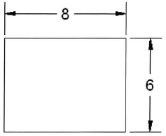
- To draw the rectangle:
- Begin the Rectangle command.
- Click in the drawing window to specify the first corner.
- For the other corner, enter @8,6 and press ENTER.
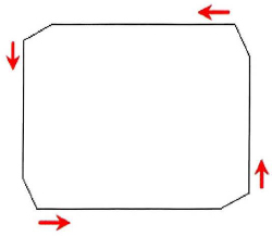
- To make a 45 degree corner using the chamfer command:
- Begin the Chamfer command.
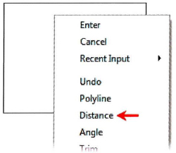
- Right-click anywhere in the drawing. Click Angle.
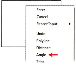
- Enter 1 and press ENTER for the chamfer length on the first line.
- Enter 45 and press ENTER to specify the chamfer angle from the first line.
- Select the first corner then the adjacent corner as indicated below.
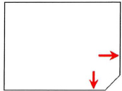
- Repeat until all 4 corners are chamfered.
- Press ENTER to exit the chamfer command.
Note: You could have used the Distance option and entered both distance lengths at 1 for the same results.
- To chamfer using the polyline option:
- Draw another 8 × 6 rectangle (see #1).
- Begin the Chamfer command.
- See that the current chamfer length is 1 and the angle is 45 degrees.
- Right-dick anywhere in the drawing. Click Polyline.
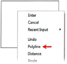
- Select the rectangle.
- All corners are chamfered.
- To chamfer using the Distance option where the distances are not equal:
- Draw another 8 × 4 rectangle.
- Begin the Chamfer command.
- Right-click anywhere in the drawing. Click Distance.
- Enter 1 for the first chamfer distance and press ENTER.
- Enter .5 for the second chamfer distance and press ENTER.
- Select the first line (1) and select the second line (2).
- Repeat the Chamfer command.
- Select the line at (3) and then select the line at (4).
Remember that the first distance is always applied to the first line you select and the second distance is applied to the second line selected.
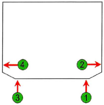
- Repeat the Chamfer command and add chamfers to all four corners as shown below.
- To chamfer using the Distance option combined with the Polyline option when the distances are not equal:
- Draw an 8 × 6 rectangle.
- Begin the Chamfer command.
- Note that the current chamfer distance 1 is 1 and distance 2 is .5.
- Right-click anywhere in the drawing. Click Polyline.

- Select the rectangle.
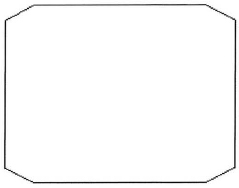
Chamfer works in a counterclockwise direction. Therefore, chamfering a polyline with non-equal distances gives you this kind of result.