
Detailed Description of the Software Exceptions
This section provides a detailed description of all of the exception types defined for the Pentium® 4 processor.
Divide-by-Zero Exception (0)
Processor Introduced In
This exception was first introduced in the 8088 processor and is implemented in the 8086, 80286, and in all subsequent IA32 processors.
Exception Class
This is an instruction Fault.
Description
The occurrence of this exception indicates that the divisor operand for a DIV or IDIV instruction is 0 or that the result cannot be represented in the number of bits specified for the destination operand.
Error Code
No error code is pushed onto the stack.
Saved Instruction Pointer
The contents of the CS:EIP register pair saved on the stack points to the instruction that generated the exception.
Processor State
A program state change does not accompany this error. The exception occurs before the faulting instruction is executed.
Debug Exception (1)
Processor Introduced In
This exception was first introduced in the 8088 processor and is implemented in the 8086, 80286, and in all subsequent IA32 processors.
Exception Class
This can be either a Trap or a Fault. The exception handler can distinguish between a trap and fault by examining the contents of DR6 and the other debug registers.
Description
The occurrence of this exception indicates that one or more of several debug exception conditions has been detected. Whether the exception is a fault or a trap depends on the condition.
| Condition | Exception Class |
|---|---|
| Instruction fetch breakpoint detected by the Debug register logic. | Fault |
| Data read or write breakpoint detected by the Debug register logic. | Trap |
| IO read or write breakpoint detected by the Debug register logic. Note this capability was introduced in the Pentium® processor. | Trap |
| General detect condition (in conjunction with in-circuit emulation). | Fault |
| Single-step exception due to EFlags[TF] = 1. | Trap |
| Due to a task switch to a task with the Trap bit set in its TSS. | Trap |
| Execution of INT 01 instruction. | Trap |
Error Code
No error code is pushed onto the stack. The handler can examine the Debug registers to determine which condition caused the exception.
Saved Instruction Pointer
In the event of a Fault, the CS:EIP value pushed onto the stack points to the instruction that generated the exception.
In the event of a Trap, the CS:EIP value pushed onto the stack points to the instruction that follows the instruction that generated the exception.
Processor State
In the event of a Fault, a program state change does not accompany the exception. The exception occurred before the faulting instruction was executed. The processor can resume normal execution upon returning from the debug exception handler.
In the event of a Trap, a program state change does accompany the exception. The instruction or task switch being executed is allowed to complete before the exception is generated. The new state of the program is not corrupted and execution of the program can continue reliably.
NMI (2)
Processor Introduced In
This interrupt (it is not an exception) was first introduced in the 8088 processor and is implemented in the 8086, 80286, and in all subsequent IA32 processors.
Exception Class
This is not an exception. Rather, it is a hardware interrupt generated by asserting the processor's NMI pin or by the receipt of an NMI interrupt message sent by the IO APIC to the processor's Local APIC (note: the APIC was not added until the advent of the P54C version of the Pentium® processor). This interrupt causes the NMI interrupt handler to be called.
Error Code
No error code is pushed onto the stack.
Saved Instruction Pointer
The processor always recognizes an NMI interrupt on an instruction boundary. The contents of CS:EIP saved on the stack point to the instruction that would have been executed next if the NMI had not occurred.
Processor State
A program or task can be safely resumed upon returning from the NMI interrupt handler, provided the interrupt handler saves the state of the processor before handling the interrupt and restores the processor's state prior to a return.
Breakpoint Exception (3)
Processor Introduced In
This exception was first introduced in the 8088 processor and is implemented in the 8086, 80286, and in all subsequent IA32 processors.
Exception Class
This is an instruction Trap.
Description
The occurrence of this exception indicates that a breakpoint instruction (INT 3) was executed. Typically, a debug software package sets a breakpoint by replacing the first opcode byte of an instruction with the opcode for the INT 3 instruction. Unlike the two byte INT nn instruction, this instruction is one byte long, so it can even be used to replace the opcode of a single byte instruction (using the INT nn instruction to do so would entail overwriting the first byte of the next instruction as well).
Starting with the 386 processor, IA32 processors implement the Debug registers, permitting software to activate up to four breakpoint access comparators. If more than four breakpoints are needed, the INT 3 instruction can be used.
This exception can also be generated by executing the INT nn instruction with an operand of 03.
Error Code
No error code is pushed onto the stack.
Saved Instruction Pointer
The contents of CS:EIP saved on the stack points to the instruction following the INT 3 instruction.
Processor State
The state of the program is unchanged because the INT 3 instruction does not affect any register or memory locations. The debugger can resume the suspended program after replacing the INT 3 instruction that caused the breakpoint with the original opcode and decrementing the EIP value stored on the stack. On returning from the debugger, program execution resumes with the replaced instruction.
Overflow Exception (4)
Processor Introduced In
This exception was first introduced in the 8088 processor and is implemented in the 8086, 80286, and in all subsequent IA32 processors.
Exception Class
This is an instruction Trap.
Description
This exception is generated when the INTO (Interrupt on Overflow) instruction is executed while EFlags[OF] = 1.
Some arithmetic instructions (e.g., ADD and SUB) perform signed and unsigned arithmetic and set either EFlags[OF] or EFlags[CF] to indicate either signed overflow or unsigned overflow condition, respectively.
Error Code
No error code is pushed onto the stack.
Saved Instruction Pointer
The CS:EIP value saved on the stack points to the instruction following the INTO instruction.
Processor State
The state of the processor is unchanged. The INTO instruction does not affect any register or any memory locations. The processor resumes normal execution upon returning from the overflow exception handler.
Array Bounds Check Exception (5)
Processor Introduced In
This exception was first introduced in the 286 processor and is implemented in all subsequent IA32 processors.
Exception Class
This is an instruction Fault.
Description
The occurrence of this exception indicates that a “bound range exceeded” fault was detected when the BOUND instruction was executed. When executed, the BOUND instruction verifies that a signed index value falls within the upper and lower bounds of an array located in memory.
Error Code
No error code is pushed onto the stack.
Saved Instruction Pointer
The CS:EIP value saved on the stack points to the BOUND instruction that generated the exception.
Processor State
A program-state change does not accompany the bounds-check fault, because the operands for the BOUND instruction are not modified. Returning from the BOUND-range-exceeded exception handler causes the BOUND instruction to be restarted.
Invalid OpCode Exception (6)
Exception Class
This is an instruction Fault.
Description
The occurrence of this exception indicates that the processor:
Attempted to execute an invalid or reserved opcode.
Attempted to execute an instruction with an operand type that is invalid for its accompanying opcode; for example, when the source operand specified for the LES instruction is not a memory location.
Attempted to execute an MMX, SSE, or SSE2 instruction on a processor that does not support MMX, SSE, or SSE2 extensions, respectively.
Attempted to execute an MMX, SSE or SSE2 instruction (with the exception of MOVNTI, PAUSE, PREFETCHH, SFENCE, LFENCE, MFENCE, or CLFLUSH) when CR0[EM] = 1.
Attempted to execute an SSE or SSE2 instruction when CR4[OSFXSR] = 0 (other than MASKMOVQ, MOVNTQ, MOVNTI, PREFETCHH, SFENCE, LFENCE, MFENCE, and CLFLUSH, or the 64-bit versions of PAVGB, PAVGW, PEXTRW, PINSRW, PMAXSW, PMAXUB, PMINSW, PMINUB, PMOVMSKB, PMULHUW, PSADBW, PSHUFW, PADDQ, and PSUBQ).
Attempted to execute an SSE or SSE2 instruction on a processor that causes a SIMD FP exception when CR4[OSXMMEXCPT] = 0.
Executed the UD2 instruction (the CS:EIP value stored on the stack points at the UD2 instruction). The UD2 instruction is guaranteed to generate an invalid opcode exception.
Detected a LOCK prefix preceding an instruction that may not be locked or one that may be locked but the destination operand is not a memory location.
Attempted to execute an LLDT, SLDT, LTR, STR, LSL, LAR, VERR, VERW, or ARPL instruction while in Real Mode or VM86 Mode.
Attempted to execute the RSM instruction while not in SMM mode.
In the IA32 processors that perform out of order speculative instruction execution (i.e., all IA32 processors starting with the Pentium® Pro), this exception is not generated until the attempted retirement of a speculatively executed invalid instruction. Decoding and speculatively executing an invalid opcode does not generate this exception. In processors earlier than the Pentium® Pro, this exception was not generated due to the prefetching and preliminary decoding of an invalid instruction.
Opcodes D6h and F1h are reserved undefined opcodes, but they do not generate an invalid opcode exception when executed.
Error Code
No error code is pushed onto the stack.
Saved Instruction Pointer
The CS:EIP value saved on the stack points to the instruction that generated the exception.
Processor State
A processor state does not change because the invalid instruction is not executed.
Device Not Available Exception (7)
Processor Introduced In
This exception was first introduced in the 286 processor and is implemented in all subsequent IA32 processors.
Exception Class
This is an instruction Fault.
Description
The DNA exception is generated when one the following conditions is detected:
The processor executed an x87 FP instruction while CR0[EM] = 1.
The processor executed an WAIT or FWAIT instruction when both CR0[MP] and CR0[TS] = 1, regardless of the setting of CR0[EM].
The processor executed an x87, MMX, SSE, or SSE2 instruction (with the exception of MOVNTI, PAUSE, PREFETCHH, SFENCE, LFENCE, MFENCE, and CLFLUSH instructions) while the CR0[TS] = 1 and CR0[EM] = 0.
Software sets CR0[EM] = 1 if the processor does not include an integrated x87 FPU and a 287 or 387 numeric coprocessor is not present on the system board. A DNA exception is then generated whenever an x87 instruction is encountered, and the exception handler acts as a FP instruction emulation routine. The exception handler reads the FP instruction pointed to by the CS:EIP value on the stack and then calls the appropriate emulation routine.
CR0[TS] = 1 indicates that a task switch has occurred since the last time an x87, MMX, SSE, or SSE2 instruction was executed, but that the contents of the x87 FPU's registers, the XMM registers, and MXCSR register were not saved when the task switch occurred. When CR0[TS] = 1 and CR0[EM] = 0, the processor generates a DNA exception when an x87, MMX, SSE, or SSE2 instruction is encountered (with the exception of the instructions listed earlier). The DNA exception handler saves the x87 FPU registers, the XMM registers, and the MXCSR register in the TSS associated with the task that last performed x87, MMX, SSE or SSE2 operations. The exception handler then sets CR0[TS] = 0 and returns to the instruction in the current task that caused the DNA exception. The x87, MMX, SSE, or SSE2 instruction encountered in the current task then executes without causing a DNA exception (because CR0[TS] = 0).
CR0[MP] is used with CR0[TS] to determine if WAIT or FWAIT instructions should generate a DNA exception. CR0[MP] extends the function of CR0[TS] to the WAIT and FWAIT instructions, thereby permitting the DNA handler to save the x87 FPU's register set before the WAIT or FWAIT instruction is executed. Software (i.e., the OS) should always set CR0[MP] = 1 on all IA32 processors from the 486DX on forward (because all of those processors have an integrated x87 FPU).
Error Code
No error code is pushed onto the stack.
Saved Instruction Pointer
The CS:EIP value saved on the stack points to the FP instruction or the WAIT or FWAIT instruction that generated the exception.
Processor State
The processor state does not change because the instruction that generated the exception is not executed.
Double Fault Exception (8)
Processor Introduced In
This exception was first introduced in the 286 processor and is implemented in all subsequent IA32 processors.
Exception Class
This is an instruction Abort.
Description
The occurrence of this exception indicates that the processor detected a second exception while calling an exception handler for a prior exception. In most cases, when the processor detects another exception while trying to call an exception handler, the two exceptions can be handled serially. In some cases, however, the processor cannot handle them serially. In that case, it generates the Double Fault exception.
Exceptions are divided into three classes: benign exceptions, contributory exceptions, and page faults (see Table 14-10 on page 301). Table 14-11 on page 302 shows the various combinations of exception classes that result in the generation of a Double Fault exception.
| Class | Vector | Description |
|---|---|---|
| Benign Exceptions and Interrupts | 1 | Debug exception. |
| 2 | Assertion of the processor's NMI hardware interrupt input. | |
| 3 | Breakpoint exception. | |
| 4 | Overflow exception. | |
| 5 | BOUND Range Exceeded exception. | |
| 6 | Invalid Opcode exception. | |
| 7 | Device Not Available exception. | |
| 9 | Coprocessor Segment Overrun exception. | |
| 16 | x87 FP Error exception. | |
| 17 | Alignment Check exception. Note that this exception was first introduced on the 486 processor. | |
| 18 | Machine Check exception. Note that this exception was first introduced on the Pentium® processor. | |
| 19 | SIMD FP exception. Note that this exception was first introduced on the Pentium® III processor. | |
| All | INT nn (where nn = the programmer-supplied vector). | |
| All | Assertion of the processor's INTR hardware interrupt input (the vector is supplied to the processor by the external interrupt controller). | |
| Contributory Exceptions | 0 | Divide by zero exception. |
| 10 | Invalid TSS exception. | |
| 11 | Segment Not Present exception. | |
| 12 | Stack Fault exception. | |
| 13 | General Protection (GP) exception. | |
| Page Faults | 14 | Page Fault exception. |
| 1st Exception | Second Exception | ||
|---|---|---|---|
| Benign | Contributory | Page Fault | |
| Benign | Handle Exceptions Serially | Handle Exceptions Serially | Handle Exceptions Serially |
| Contributory | Handle Exceptions Serially | Generate a Double Fault | Handle Exceptions Serially |
| Page Fault | Handle Exceptions Serially | Generate a Double Fault | Generate a Double Fault |
Since the Double Fault exception is an abort type exception, the interrupted program or task cannot be safely restarted or resumed. The Double Fault handler collects diagnostic information about the state of the machine and, when possible, shuts the application and/or system down gracefully or restarts the system.
If the processor encounters another exception while attempting to call the Double Fault handler, it enters Shutdown Mode. This is sometimes unofficially referred to as a Triple Fault condition.
Shutdown Mode
In Shutdown Mode, the processor stops executing instructions until one of the following is detected:
an NMI interrupt.
an SMI interrupt.
a hardware reset.
the assertion of the processor's INIT# input.
Upon entering Shutdown Mode, the processor generates the Special transaction on its FSB and outputs the Shutdown message on its Byte Enable outputs. This informs the platform logic external to the processor that the processor has entered the Shutdown state. In response, the platform logic may take an action such as:
Turn on an indicator light on the front panel.
Generate an NMI interrupt. In the NMI handler, the programmer obtains status information from the chipset, determines that the processor has shutdown, records diagnostic information, and takes one of the following actions:
- Commands the chipset to assert RESET# to the processor.
- Commands the chipset to assert INIT# to the processor.
- Commands the chipset to assert SMI# to the processor.
If the shutdown occurs while the processor is executing the NMI interrupt handler, the processor can only be restarted by asserting RESET# to the processor.
Error Code
The processor always pushes an error code of 0 onto the stack of the Double Fault handler.
Saved Instruction Pointer
The CS:EIP value saved on the stack is undefined.
Processor State
The processor state following a Double Fault exception is undefined. The interrupted program or task therefore cannot be safely resumed or restarted.
Coprocessor Segment Overrun Exception (9)
Processor Introduced In
This exception was first introduced in the 286 processor and was implemented in the 386 and early versions of the 486 processor (prior to the integration of the FPU onto the processor die).
Exception Class
This is an instruction Abort.
Description
Reserved starting with the 486DX. The occurrence of this exception indicates that the 386 processor detected a Page Fault or Segment Not Present exception while transferring the middle portion of an operand to the 387 math coprocessor. Starting with the 486DX processor, this condition is reported as a General Protection exception.
Error Code
No error code is pushed onto the stack.
Saved Instruction Pointer
The CS:EIP value saved on the stack points to the instruction that generated the exception.
Processor State
The processor state after a coprocessor segment overrun exception is undefined. The interrupted program or task therefore cannot be safely resumed or restarted. The only action that the exception handler can take is to save CS:EIP and reinitialize the x87 FPU using the FNINIT instruction.
Invalid TSS Exception (10)
Processor Introduced In
This exception was first introduced in the 286 processor and is implemented in all subsequent IA32 processors.
Exception Class
This is an instruction Fault.
Description
The occurrence of this exception indicates that a task switch was attempted and that invalid information was detected in the TSS for the target task. Table 14-12 on page 305 shows the conditions that will cause an invalid-TSS exception to be generated. In general, these invalid conditions result from protection violations for:
The TSS descriptor.
The LDT pointed to by the TSS.
Any of the segments referenced by the TSS.
| Error Code Index Field Contains | Invalid Condition |
|---|---|
| TSS segment selector index | TSS segment limit less than 67H for 32-bit TSS or less than 2CH for 16-bit TSS. |
| LDT segment selector index | Invalid LDT or LDT not present. |
| Stack-segment selector index | Stack-segment selector exceeds descriptor table limit. |
| Stack-segment selector index | Stack segment is not writable. |
| Stack-segment selector index | Stack segment DPL / CPL. |
| Stack-segment selector index | Stack-segment selector RPL / CPL. |
| Code-segment selector index | Code-segment selector exceeds descriptor table limit. |
| Code-segment selector index | Code segment is not executable. |
| Code-segment selector index | Nonconforming code segment DPL / CPL. |
| Code-segment selector index | Conforming code segment DPL greater than CPL. |
| Data-segment selector index | Data-segment selector exceeds descriptor table limit. |
| Data-segment selector index | Data segment not readable. |
This exception can be generated either in the context of the original task or in that of the target task. Until the processor has completely verified the presence of the target task's TSS, the exception is generated in the context of the original task. Once the existence of the target task's TSS is verified, the task switch is considered complete. Any invalid-TSS conditions detected after this point are handled in the context of the new task. A task switch is considered complete when the Task Register (TR) is loaded with the segment selector for the target task's TSS and, if the switch is due to a CALL, an interrupt or an exception, the Link field of the new TSS has been updated with the TSS selector for the calling or interrupted task. For more information, refer to “Task Switch Details” on page 196.
Entry 10d in the IDT must contain a Task Gate pointing to a task that will act as the Invalid TSS handler. Handling this exception inside the faulting TSS context is not recommended because the processor state may not be consistent.
Error Code
An error code containing the segment selector index for the segment descriptor that caused the violation is pushed onto the stack of the exception handler. If the EXT flag is set (see Figure 14-13 on page 290 and Table 14-8 on page 287), it indicates that the exception was caused by an event external to the currently running program (e.g., if an external hardware interrupt handler called using a Task Gate attempted a task switch using an invalid target TSS).
Saved Instruction Pointer
If the exception was detected before the task switch was carried out, the CS:EIP value saved on the stack points to the instruction that invoked the task switch. If the exception was detected after the task switch, the CS:EIP value saved on the stack points to the first instruction of the new task.
Processor State
Whether or not the Invalid TSS handler can recover from the fault depends on the error condition than causes the fault.
If an invalid TSS exception occurs during a task switch, it can occur before or after the commit-to-new-task point (see Figure 11-3 on page 199). If it occurs before the commit point, no processor state change occurs. If it occurs after the commit point (after the segment descriptor information for the new segment selectors have been loaded in the segment registers), the processor will load all the state information from the new TSS into its register set before it generates the exception. The processor first loads all of the segment registers with the segment selectors from the TSS, loads the respective segment descriptors from the GDT and/or LDT, and then checks the descriptors for validity. If an Invalid TSS exception is detected, the remaining segment registers are loaded but not checked for validity and therefore may not be usable for referencing memory.
The Invalid TSS handler should assume that using the segment selectors found in the CS, SS, DS, ES, FS, and GS registers may result in the generation of another exception. For this reason, the exception handler should load all segment registers with new values before trying to resume the new task; otherwise, GP exceptions may result later under conditions that make diagnosis more difficult.
Segment Not Present Exception (11)
Processor Introduced In
This exception was first introduced in the 286 processor and is implemented in all subsequent IA32 processors.
Exception Class
This is an instruction Fault.
Description
The occurrence of this exception indicates that the Present bit of a segment descriptor or gate descriptor = 0, indicating that the descriptor is not valid. This exception can occur during any of the following operations:
While attempting to load the CS, DS, ES, FS, or GS registers (note that detection of a segment not present condition while loading the SS register results in the generation of a Stack Fault exception).
While attempting to load the LDTR using an LLDT instruction. Detection of a not-present LDT while loading the LDTR during a task switch operation causes an Invalid TSS exception to be generated.
When executing the LTR instruction and the TSS is marked not present.
While attempting to use a gate descriptor or a TSS descriptor that is marked as not present, but is otherwise valid.
Much like Paging, an OS could use the Segment Not Present exception in the same manner as a Page Fault exception to implement on-demand loading of segments of information into memory from a mass storage device.
Error Code
An error code containing the segment selector index for the segment descriptor that caused the violation is pushed onto the stack of the exception handler. If the EXT flag is set (see Figure 14-13 on page 290 and Table 14-8 on page 287), it indicates that the exception was caused by NMI or INTR wherein the interrupt vector selected an IDT entry that contained a descriptor with the Present bit = 0. The IDT bit in the error code = 1 if the error code refers to an IDT entry.
Saved Instruction Pointer
The CS:EIP value saved on the stack normally points to the instruction that generated the exception. However, if the exception occurred while the processor was loading the segment descriptors using the segment selectors in a new TSS, the CS:EIP value on the stack points to the first instruction in the new task. If the exception occurred while accessing a gate descriptor, the CS:EIP value saved on the stack points to the instruction that resulted in the descriptor being accessed (e.g., a CALL instruction that selects a Call Gate).
Processor State
If this exception occurs as the result of loading a register (CS, DS, SS, ES, FS, GS, or LDTR), a processor state change does occur (the register is not loaded). Recovery from this exception is affected by loading the missing segment into memory, updating the segment descriptor and marking it as present.
If the exception occurs while accessing a gate descriptor, a processor state change does not occur. Recovery from this exception is accomplished by creating a valid gate descriptor and then re-executing the instruction that selected the gate descriptor.
If the exception occurs during a task switch, it can occur before or after the commit-to-new-task point (see Figure 11-3 on page 199). If it occurs before the commit point, no processor state change occurs. If it occurs after the commit point, the processor loads its registers from the new TSS (without performing any additional limit, present, or type checks) before it generates the exception. The exception handler therefore cannot rely on the validity of the segment selectors in the segment registers.
The handler should assume that using the segment selectors found in the CS, SS, DS, ES, FS, and GS registers may result in the generation of another exception. For this reason, the exception handler should load all of the segment registers with new values before trying to resume the new task; otherwise, GP exceptions may result later under conditions that make diagnosis more difficult.
Stack Exception (12)
Processor Introduced In
This exception was first introduced in the 286 processor and is implemented in all subsequent IA32 processors.
Exception Class
This is an instruction Fault.
Description
The occurrence of this exception indicates that one of the following stack related conditions was detected:
When a limit violation is detected during an operation that refers to the SS register. Operations that can cause a limit violation include stack-oriented instructions such as POP, PUSH, CALL, RET, IRET, ENTER, and LEAVE, as well as other memory references which implicitly or explicitly use the SS register (e.g., MOV AX, [BP+6] or MOV AX, SS:[EAX+6]). The ENTER instruction generates this exception when there is not enough stack space for allocating local variables.
When a stack segment not-present condition is detected while loading the SS register. This can occur during:
- a task switch.
- the execution of a CALL instruction to a procedure at a different privilege level.
- a return to a procedure at a different privilege level.
- the execution of the LSS instruction.
- the execution of a MOV or POP instruction to the SS register.
Recovery from this fault can be accomplished by either:
Extending the limit of the stack segment (on a limit violation).
Loading the missing stack segment into memory (on a not present condition).
Error Code
If the exception is caused by a stack segment not present or by an overflow of the new stack during an inter-privilege level call, the error code saved on the stack (see Figure 14-13 on page 290) contains a segment selector for the segment that caused the exception. The exception handler can test the Present bit in the segment descriptor pointed to by the segment selector to determine the cause of the exception.
For a limit violation (on a stack segment already in use) the error code saved on the stack is 0.
Saved Instruction Pointer
The CS:EIP value saved on the stack generally points to the instruction that generated the exception. However, if the exception was caused by an attempt to load a segment selector into the SS register that selects a descriptor with the Present bit = 0 during a task switch, the CS:EIP value saved on the stack points to the first instruction of the new task.
Processor State
A processor state change does not generally accompany a Stack Fault exception, because the instruction that caused the fault is not executed. The instruction can therefore be re-executed after the exception handler has corrected the Stack Fault condition.
If a Stack Fault occurs during a task switch, it occurs after the commit-to-new-task point (see Figure 11-3 on page 199). The processor loads its registers from the new TSS (without performing any additional limit, present, or type checks) before it generates the exception.
The handler should therefore assume that using the segment selectors found in the CS, SS, DS, ES, FS, and GS registers may result in the generation of another exception. For this reason, the exception handler should load all of the segment registers with new values before trying to resume the new task; otherwise, GP exceptions may result later under conditions that make diagnosis more difficult.
General Protection (GP) Exception (13)
Processor Introduced In
This exception was first introduced in the 286 processor and is implemented in all subsequent IA32 processors.
Exception Class
This is an instruction Fault.
Description
The occurrence of this exception indicates that the processor detected a General Protection violation. The conditions that can cause this exception comprise all of the protection violations that do not cause another type of exception to be generated. Any of the following conditions will result in the generation of a General Protection exception:
Exceeding the segment limit when accessing the CS, DS, ES, FS, or GS segments.
Exceeding the segment limit when referencing a descriptor table (i.e., the GDT, LDT or IDT; except during a task switch or a stack switch).
Transferring execution to a segment wherein the attributes define it as not executable.
An attempt to write to a code segment or to a read-only data segment.
An attempt to perform a data read from an execute-only code segment.
Loading SS with a selector for a read-only segment (unless the selector is read from the new TSS during a task switch, in which case an Invalid TSS exception occurs).
Loading SS, DS, ES, FS, or GS with a selector for a system segment (i.e., the descriptor's S bit = 0).
Loading DS, ES, FS, or GS with a selector for an execute-only code segment.
Loading SS with a selector for an executable code segment or with a null segment selector.
Loading CS with a selector for a data segment or for a null segment selector.
Accessing memory using DS, ES, FS, or GS when it contains a null segment selector.
Switching to a busy task during a call or jump that selects a TSS.
Switching to an available (non-busy) task during the execution of an IRET instruction.
Using a selector on a task switch that points to a TSS descriptor in the current task's LDT. TSS descriptors can only reside in the GDT.
Exceeding the maximum instruction length limit of 15 bytes (this only can occur when redundant prefixes are placed before an instruction).
Loading CR0 so as to enable paging and disable Protected Mode (CR0[PG] = 1 and CR0[PE] = 0).
Loading CR0 so CR0[NW] = 1 and CR0[CD] = 0 (this is a reserved combination).
When the vector selects an IDT entry that does not contain an Interrupt Gate, Trap Gate, or a Task Gate.
An attempt to access an interrupt or exception handler through an Interrupt Gate or a Trap Gate from VM86 mode when the handler's code segment DPL is greater than 0.
An attempt to write a 1 into a reserved bit of CR4 (CR4 is only present in later model 486s and subsequent IA processors).
An attempt to execute a privileged instruction when the CPL is not equal to 0.
An attempt to write to a reserved bit in an MSR (MSRs are only present in the Pentium® and subsequent IA processors.
An attempt to access a gate that contains a null segment selector.
Executing the INT nn instruction when the CPL > the DPL of the referenced Interrupt Gate, Trap Gate, or Task Gate.
The segment selector in a Call Gate, Interrupt Gate, or a Trap Gate does not point to a code segment.
The segment selector specified as the operand of the LLDT instruction selects an entry in the LDT rather than the GDT, or that selects a descriptor in the GDT that is not an LDT descriptor.
The segment selector specified as the operand of the LTR instruction selects an entry in the LDT rather than the GDT, or that selects a TSS descriptor with its Busy bit = 1.
The target code segment selector for a CALL, jump, or RET is null.
If CR4[PAE] and/or CR4[PSE] =1 and the processor detects any reserved bits in a PDPT entry set to 1 (PAE was first implemented in the Pentium® Pro and PSE was first implemented in the Pentium®). These bits are checked during any write to CR0, CR3, or CR4 (CR4 is implemented in later model 486s and subsequent IA32 processors) that causes a reloading of the PDPT entry.
An attempt to set any of the reserved bits in the MXCSR register = 1.
Executing an SSE or SSE2 instruction that attempts to access a 128-bit memory location using an address that is not aligned on a 16-byte boundary when the instruction requires 16-byte alignment (SSE was first implemented on the Pentium® III and SSE2 on the Pentium® 4). This condition also applies to the stack segment.
Violating any of the privilege rules described in Chapter 4 of Intel®'s IA32 Intel® Architecture Software Developer's Manual Volume 3: System Programming Guide.
A program or task can be restarted following any GP exception. If the exception occurs while attempting to call an interrupt handler, the interrupted program within which the exception occurred can be restarted, but the interrupt may be lost.
Error Code
If the fault condition was detected while loading a segment descriptor, the error code (see Figure 14-13 on page 290 and Table 14-8 on page 287) contains a segment selector index or an IDT vector number for the offending descriptor; otherwise, the error code saved on the stack = 0. The source of the selector in an error code may be any of the following:
An operand of the instruction.
A selector from a gate which was selected by an instruction.
A selector from a TSS involved in a task switch.
An IDT vector number.
Saved Instruction Pointer
The CS:EIP value saved on the stack points to the instruction that generated the exception.
Processor State
In general, a processor state change does not result from a GP exception (because the invalid instruction or operation is not executed). A GP exception handler can be designed so as to correct any of the conditions that can cause a GP exception and then resume the interrupted program or task.
If a GP exception occurs during a task switch, it can occur before or after the commit-to-new-task point (see Figure 11-3 on page 199). If it occurs before the commit point, no processor state change occurs. If it occurs after the commit point, the processor loads its registers from the new TSS (without performing any additional limit, present, or type checks) before it generates the exception.
The handler should therefore assume that using the segment selectors found in the CS, SS, DS, ES, FS, and GS registers may result in the generation of another exception. For this reason, the exception handler should load all of the segment registers with new values before trying to resume the new task; otherwise, GP exceptions may result later under conditions that make diagnosis more difficult.
Page Fault Exception (14)
Processor Introduced In
This exception was first introduced in the 386 processor and is implemented in all subsequent IA32 processors.
Exception Class
This is an instruction Fault.
Description
The occurrence of this exception indicates that the processor detected one of the following conditions while attempting to translate a linear memory address into a physical memory address:
The page Present bit in the selected PDE or the PTE = 0, indicating that the selected Page Table or the selected physical page is not present in memory. In this case, the Page Fault exception handler can obtain the missing Page Table and/or information page from mass storage, place it in memory, fill in the selected PDE and/or PTE, and then re-execute the instruction that caused the Page Fault.
The procedure attempting to access a page does not have sufficient privilege to do so. It's OS- and situation-specific whether or not the Page Fault exception handler fixes this problem (by adjusting the U/S bit in the selected PDE and/or PTE) and then permits the access.
The currently executing program has a privilege level other than 0 and attempted to write to a read-only page. It should be noted that, in the 386 a supervisor level program (i.e., with a privilege level of 0, 1 or 2) can write to a read-only page without causing a Page Fault exception. See the next bullet item for information on IA32 processors after the 386.
Starting with the 486 processor, all IA32 processors implement CR0[WP]. When CR0[WP] = 1, a Page Fault exception is generated when a supervisor level program (i.e., with a privilege level of 0, 1 or 2) attempts to write to a read-only page wherein the U/S bit = 0 (access permitted by programs executing at privilege level 3).
The attempted access selected a PDE wherein one or more of the reserved bits are set to one.
Error Code
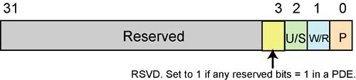
An error code is pushed onto the stack when a Page Fault exception is detected. The error code has a special format (see Figure 14-15 on page 315) that provides the following information to the exception handler:
P bit:
- -
P = 1.
The exception was due to P = 0 in either the selected PDE or PTE.
- -
P = 0.
The exception was due to either an access rights violation or the detection of one or more reserved bits set to one in the selected PDE.
- -
P = 1.
The exception was due to P = 0 in either the selected PDE or PTE.
The W/R bit indicates whether the memory access that caused the exception was a read (0) or write (1).
The U/S flag indicates whether the offending program was executing at user mode privilege level (3) or at the supervisor mode privilege level (0, 1, or 2).
- 0 = Supervisor privilege level.
- 1 = User mode privilege level.
When set to one, the RSVD bit indicates that the processor detected one or more reserved bits set to one in the selected PDE. This detection feature is only enabled when CR4[PAE] and/or CR4[PSE] = 1:
- CR4[PSE] was first implemented in the Pentium®, was migrated backwards into the later versions of the 486, and is present in all subsequent IA32 processors.
- CR4[PAE] was first implemented in the Pentium® Pro and is present in all subsequent IA32 processors.
Figure 14-15. Page Fault Exception Error Code Format
CR2
When a Page Fault exception is detected, the 32-bit linear address that generated the exception is automatically latched into CR2. The Page Fault handler uses this address to perform a lookup in the Page Directory and/or in the selected Page Table. If another Page Fault could occur during execution of the Page Fault handler, the handler must push the contents of CR2 onto the stack before the second Page Fault occurs.
If a Page Fault is caused by a page-level protection violation, the Accessed bit in the PDE is set when the fault occurs. The behavior of IA32 processors regarding the Accessed bit in the corresponding PTE is model specific and is not architecturally defined.
Saved Instruction Pointer
The CS:EIP value saved on the stack generally points to the instruction that generated the exception. If the Page Fault exception occurred during a task switch, the CS:EIP value on the stack may point to the first instruction of the new task.
Processor State
The More Common Case
The processor state doesn't normally change when a Page Fault exception is generated (because the instruction that caused the exception was not executed). After the Page Fault exception handler has corrected the violation (e.g., by loading the missing page into memory), execution of the program or task can be resumed.
Page Fault During a Task Switch
When a Page Fault exception is generated during a task switch, the processor state may change, however. During a task switch, a Page Fault exception can occur during any of following operations:
While writing the contents of the processor's register set into the TSS of the task that is being departed from.
While reading the GDT to locate the TSS descriptor of the destination task.
While reading the TSS of the destination task.
While reading the segment descriptors associated with segment selectors from the destination task.
While reading the LDT of the destination task to verify the segment register images stored in the new TSS.
In the last two cases the exception occurs in the context of the new task. CS:EIP points to the first instruction of the new task, not to the instruction which caused the task switch (or the last instruction to be executed, in the case of an interrupt). If the OS permits Page Faults to occur during task switches, the Page Fault handler should be called through a Task Gate.
If a Page Fault occurs during a task switch, the processor loads its register set from the new TSS (without performing any additional limit, present, or type checks) before it generates the exception. The handler should therefore assume that using the segment selectors found in the CS, SS, DS, ES, FS, and GS registers may result in the generation of another exception. For this reason, the exception handler should load all of the segment registers with new values before trying to resume the new task; otherwise, GP exceptions may result later under conditions that make diagnosis more difficult.
Page Fault During a Stack Switch
Software written for 16-bit x86 processors often used a pair of instructions to change to a new stack. As an example:
MOV SS, AX
MOV SP, StackTop
When executing this code on an IA32 processor, it is possible to detect a Page Fault, GP exception, or Alignment Check exception after the first instruction completes but before the ESP register has been loaded. At this point, the new stack segment is being used with the old stack pointer. Very bogus!
If the exception handler is called at the same privilege level and within the same task, the processor will use the bogus stack pointer. However, the processor will not use the inconsistent stack pointer if the exception handler is implemented as another task or as a more privileged procedure.
In an OS that handles Page Fault, GP, or Alignment Check exceptions within the faulting task (in other words, the handlers are pointed to by Trap Gates or Interrupt Gates, rather than by Task Gates), when software that executes at the same privilege level as the exception handler wishes to change to a new stack it should use the LSS instruction rather than a pair of MOV instructions (as illustrated earlier in this chapter). When the exception handler executes at privilege level 0 (as is most often the case), the problem is limited to procedures or tasks that run at privilege level 0, typically the OS kernel.
Vector 15
Vector 15d is reserved in all IA32 processors up to and including the Pentium® 4, Pentium® 4 Xeon, and the Pentium® M.
FPU Exception (16)
Processor Introduced In
This exception was first introduced in the 286 processor and is implemented in all subsequent IA32 processors.
Exception Class
This is an instruction Fault.
Description
The occurrence of this exception indicates that the x87 FPU has detected a FP error. CR[NE] =1 enables the generation of this exception.
The x87 FPU can detect and report six types of FP error conditions:
Invalid operation:
- Stack overflow or underflow.
- Invalid arithmetic operation.
Divide-by-zero.
Denormalized operand.
Numeric overflow.
Numeric underflow.
Inexact result (precision).
There are two register bits associated with each of these error types:
A corresponding Mask bit in the FPU Control register.
A corresponding status bit in the FPU Status register.
In addition, the Summary Error (SE) bit in the FPU Status register is set to one whenever any of the unmasked error conditions are detected.
Handling of Masked Errors
When the FPU detects an error type that is currently masked, it sets the respective error status bit in the FPU Status register. However, it does not set the Summary Error (SE) status bit in the Status register, nor does it generate a a FPU exception. Rather, the processor takes a default set of actions based on the error type detected and continues with program execution. Table 14-13 on page 318 defines the default set of actions taken when a masked error type is detected.
Handling of Unmasked Errors
This description assumes that CR0[NE] = 1.
When the FPU detects an error type that is currently unmasked (in the FCW register), it sets the respective error status bit in the FPU Status register (FSW). However, it does not immediately set the Summary Error (SE) status bit in the Status register (FSW), nor does it immediately generate a FPU exception.
Rather, it waits until it fetches and decodes the next “waiting” x87 FPU instruction or WAIT/FWAIT instruction in the program's instruction stream. At that time, before actually executing the current instruction, if any of the unmasked error type status bits are set to one in the Status register (FSW), it sets the Summary Error (SE) status bit in the Status register and generates a FPU exception.
x87 FPU errors incurred by a previously executed computational FPU instruction are not reported via the SE bit or the exception if the processor subsequently executes any of the “non-waiting” x87 FPU instructions, which include the FNINIT, FNCLEX, FNSTSW, FNSTSW AX, FNSTCW, FNSTENV, and FNSAVE instructions. They also are not reported on execution of either of the state management instructions, FXSAVE or FXRSTOR.
The FPU exception handler can be designed to permit recovery from any of the error types.
Error Code
No error code is pushed onto the stack.
Saved Instruction Pointer
The CS:EIP value saved on the stack points to the FP or WAIT/FWAIT instruction that was about to be executed when the exception was generated. This is not the instruction that generated the error. The address of the offending instruction is automatically latched into the FPU's 48-bit Instruction Pointer register (in CS:EIP format). In addition, if a memory-based data operand is associated with the instruction, the address is automatically latched into the FPU's 48-bit Data Pointer register (in xS:offset format, where xS = D, E, F, or G and the offset is a 32-bit pointer).
Processor State
Generally, a processor state change results from a FPU exception (because the handling of the exception is delayed until the next waiting x87 FP or WAIT/FWAIT instruction following the offending instruction. The x87 FPU saves sufficient information about the error condition in its register set to allow recovery from the error and re-execution of the faulting instruction.
In the situation wherein an instruction is dependent on the results of a previously-executed FP instruction, a WAIT or FWAIT instruction can be inserted in front of the dependent instruction. This will force a yet-to-be-reported x87 FPU error to generate an exception and be handled before the dependent instruction is executed.
Alignment Check Exception (17)
Processor Introduced In
This exception was first introduced in the 486 processor and is implemented in all subsequent IA32 processors.
Exception Class
This is an instruction Fault.
Description
The occurrence of this exception indicates that the processor detected an unaligned memory operand (refer to “Misaligned Transfers Affect Performance” on page 43 and “Alignment Is Important!” on page 43) when alignment checking is enabled. Alignment checking is only performed for data accesses within data or stack segments (not for accesses in code or system segments). Table 14-14 lists the alignment requirements of various data types recognized by the processor.
| Data Type | Address Must Be Divisible By |
|---|---|
| Word (16 bits) | 2 |
| Dword (32 bits) | 4 |
| 32-bit Single Precision FP number | 4 |
| 64-bit Double Precision FP number | 8 |
| 80-bit Double Extended Precision FP number | 8 |
| Qword (64-bits) | 8 |
| Double qword (128 bits) | 16 |
| Segment Selector (16 bits) | 2 |
| 32-bit Far Pointer | 2 |
| 48-bit Far Pointer | 4 |
| 32-bit Pointer | 4 |
| GDTR, IDTR, LDTR, or Task Register Contents | 4 |
| FSTENV/FLDENV Save Area | 4 or 2, depending on the operand size. |
| FSAVE/FRSTOR Save Area | 4 or 2, depending on the operand size. |
| Bit String | 2 or 4 depending on the operand-size attribute. |
The Alignment Check exception is only generated on a misaligned access attempted on a data type that should be aligned on word, dword, and qword address boundaries. A GP exception is generated when an access is attempted on a 128-bit data type that is not aligned on an address divisible by 16.
Alignment Checking is enabled when all of the following are true:
The privilege level of the currently executing program (i.e., its CPL) = 3 and the current task is running in either Protected Mode or VM86 mode.
Implicit Privilege Level 0 Accesses
Memory accesses that are always performed at privilege level 0 (e.g., segment descriptor loads), never result in an Alignment Check exception, even when generated by an access initiated by a program executing at privilege level 3.
Storing GDTR, LDTR, IDTR or TR
An attempt to store the contents of the GDTR, IDTR, LDTR, or the TR in memory while at privilege level 3 can result in an Alignment Check exception. The fault can be avoided by storing the register's contents into memory starting at an address that is divisible by two.
FP/MMX/SSE/SSE2 Save and Restore Accesses
The FXSAVE and FXRSTOR instructions save and restore the contents of the x87 FPU register set and the SSE/SSE2 register set in a 512-byte data structure in memory. The start address specified must be divisible by 16. If the Alignment Check exception is enabled and the CPL of the currently executing program = 3, a misaligned memory operand can cause either:
An Alignment Check exception. If the AC exception is enabled and the CPL = 3, generation of the AC exception is not guaranteed and can be model-specific. In implementations where the AC exception is not generated, a GP exception is generated instead. In addition, the alignment granularity may also vary with implementation. As an example, in a given implementation, an AC exception might be generated wherein the start address is not aligned on an address divisible by two, whereas a GP exception might result for other misalignments types (4-, 8-, or 16-byte misalignments).
A GP exception is generated for an illegal memory operand effective address in the CS, DS, ES, FS or GS segments. If the AC exception is disabled, a GP exception is generated if the start memory address specified is not aligned on a 16-byte boundary.
MOVUPS and MOVUPD Accesses
The MOVUPS (Move Unaligned Packed SP FP value) and MOVUPD (Move Unaligned Packed DP FP value) instructions perform a 128-bit unaligned load or store. They do not generate GP exceptions when an operand is not aligned on a 16-byte boundary. If alignment checking is enabled, 2-, 4-, and 8-byte misalignments are detected and result in the generation of an Alignment Check exception.
FSAVE and FRSTOR Accesses
The start memory address specified as the operand of the FSAVE and FRSTOR instructions can result in the generation of an alignment check exception. These instructions are rarely used by application programs.
Error Code
An error code of 0 is pushed onto the stack.
Saved Instruction Pointer
The CS:EIP value stored on the stack points to the instruction that generated the exception.
Processor State
A processor state change does not result from an AC exception (because the instruction is not executed).
Machine Check Exception (18)
Processor Introduced In
This exception was first introduced in the Pentium® processor and is implemented in all subsequent IA32 processors.
Exception Class
This is an instruction Abort.
Description
The processor's ability to generate a Machine Check exception is enabled by setting CR4[MCE] = 1.
The occurrence of this exception indicates that the processor detected a serious internal hardware error (e.g., an unrecoverable ECC error when accessing an internal cache or TLB) or a serious error on the FSB, or that another entity on the FSB (e.g., the chipset) asserted a signal:
on the Pentium® 4, Pentium® 4 Xeon, and the Pentium® M, the MCERR# or BINIT# signal;
on the P6 processor family, the BINIT# signal;
on the Pentium®, the BUSCHK# signal
to the processor indicating that it detected a serious bus-related error (e.g., a parity error). The circumstances under which the Machine Check (MC) exception is generated and how the MCA register set is implemented is processor design-specific. The CPUID instruction is used to determine whether this feature is present.
For a detailed description of the Machine Check Architecture, refer to:
“Machine Check Architecture (MCA)” on page 504 for a description of the Pentium® MCA.
“MCA Enhanced” on page 588 for a description of the P6 MCA.
“The Machine Check Architecture” on page 1363 for a description of the Pentium® 4 MCA.
Error Code
No error code is pushed onto the stack. The related error information is latched into the MCA (Machine Check Architecture) MSRs.
Saved Instruction Pointer
On the Pentium® 4, Pentium® 4 Xeon and Pentium® M processors, the information saved in the extended Machine Check state registers (refer to “The Extended MC State MSRs” on page 1364) is directly associated with the error that caused the Machine Check exception to be generated.
On the P6 and Pentium® 4 family processors, if the MCG_STATUS[EIPV] (EIP Valid) bit = 1, the CS:EIP value saved on the stack is directly associated with the error that caused the exception to be generated. If the bit = 0, the CS:EIP value on the stack may or may not be associated with the error.
On the Pentium® processor, the CS:EIP value saved on the stack may or may not be associated with the error.
Processor State
On the Pentium® 4, Pentium® 4 Xeon, the P6 family, and the Pentium® processors, a processor state change always results from a Machine Check exception. Information about the exception can be collected from the Machine Check MSRs, but, generally speaking, the interrupted program cannot be restarted.
If the Machine Check exception is not enabled (CR4[MCE] = 0), a Machine Check condition causes the processor to enter the Shutdown state (for more information refer to “Shutdown Mode” on page 302).
SIMD Floating-Point Exception (19)
Processor Introduced In
This exception was first introduced in the Pentium® III processor and is implemented in all subsequent IA32 processors.
Exception Class
This is an instruction Fault.
Description
The occurrence of this exception indicates that the processor has detected an SSE or SSE2 SIMD FP exception. For this exception to be generated when a specific error type occurs, the respective mask bit (associated with the error type) in the MXCSR register must = 0 (i.e., unmasked).
There are six classes of numeric error conditions that can be detected while executing an SSE or SSE2 SIMD FP instruction:
Invalid operation.
Divide-by-zero.
Denormal operand.
Numeric overflow.
Numeric underflow.
Inexact result (Precision).
The invalid operation, divide-by-zero, and denormal-operand exceptions are pre-computation exceptions; that is, they are detected before any arithmetic operation occurs. The numeric underflow, numeric overflow, and inexact result exceptions are post-computational exceptions.
When a SIMD (Single Instruction operating upon Multiple Data items; see “MMX Capability” on page 519 for more information) FP exception occurs, the processor does one of the following:
It handles the exception automatically by producing the most reasonable result and allowing program execution to continue undisturbed. This is the response to masked error types.
It generates a SIMD FP exception, invoking a software exception handler. This is the response to unmasked error types.
Each of the six SIMD FP error conditions has two associated bits in the MXCSR register:
A mask bit which, when set to one, prevents the associated error type from generating an exception.
A status bit which, when set to one, indicates that the respective error type was detected.
If an error type is masked, the processor takes an appropriate automatic default action and continues with the computation. If the exception is unmasked and the OS implements a SIMD FP exception handler (as indicated by the OS having set CR4[OSXMMEXCPT] = 1), and the error type is detected, the exception handler is invoked through a SIMD FP exception. If the error type is unmasked and CR4[OSXMMEXCPT] = 0 (indicating that the OS does not implement a SIMD FP exception handler), an Invalid Opcode exception is generated rather than a SIMD FP exception.
Unlike x87 FPU exceptions, SIMD FP exceptions are precise and occur immediately.
If a SIMD FP error of a specific type occurs while recognition of that error type is masked and the recognition of that error type is subsequently unmasked, then no exception is generated when the error type is unmasked.
When SSE or SSE2 SIMD FP instructions operate on two or four data operands packed into an XMM register, multiple SIMD FP error conditions may be detected. If the operation performed on each of the packed data operands results in no more than one error per operand, the error status bits associated with each of those errors are set in the MXCSR register.
However, if the operation performed on any of the packed data operands results in the detection of two or more error conditions, only one exception condition is reported (and the precedences are shown in Table 14-15 on page 326). This sometimes results in a higher priority error being reported and a lower priority error being ignored.
| Priority | Description |
|---|---|
| 1 (highest) | Invalid operation error due to SNaN operand (or any NaN operand for maximum, minimum, or certain compare and convert operations). |
| 2 | QNaN operand. Though a QNaN, this is not an error, the handling of a QNaN operand has precedence over lower priority errors. For example, a QNaN divided by zero results in a QNaN, not a divide-by-zero error. |
| 3 | Any other invalid operation error not mentioned above or a divide-by-zero error. If masked, then instruction execution continues, and a lower priority error can occur as well. |
| 4 | Denormal operand error. If masked, then instruction execution continues, and a lower priority error can occur as well. |
| 5 | Numeric overflow and underflow errors, possibly in conjunction with the inexact result error. If masked, then instruction execution continues, and a lower priority error can occur as well. |
| 6 (lowest) | Inexact result error. |
Exception Error Code
No error code is pushed onto the stack.
Saved Instruction Pointer
The CS:EIP value saved on the stack points to the SSE or SSE2 instruction that caused the SIMD FP exception.
Processor State
The processor state does not change as the result of a SIMD FP exception. The handling of the exception is immediate unless the detected error is masked. The state information available in the register set and on the stack is often sufficient to allow recovery from the error and re-execution of the offending instruction.