
General Segment Descriptor Format
Figure 7-9 on page 122 illustrates the general format of a segment descriptor. The sections that follow provide a detailed description of each descriptor element.
Figure 7-9. General Format of a Segment Descriptor
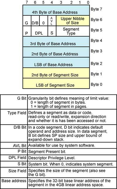
It should be noted, however, that there are a number of variations on the segment descriptor and they are covered in the chapters that follow.
Granularity Bit
The granularity bit tells the processor how to interpret the segment descriptor size field (also referred to as the limit):
G = 0 indicates that the size field specifies the segment size in bytes.
G = 1 indicates that the size is specified in pages of 4KB each.
The size field is 20 bits wide, so depending on the state of the granularity bit, the segment's size may be defined in the range from one to 1048576d (i.e., 1M) bytes or pages in length (1048576d pages = 4GB).
Segment Base Address Field
The 32-bit base address field is used to specify the start segment address within the 4GB linear address space. It can start at any address from 00000000h through FFFFFFFFh.
Segment Size Field
See the “Granularity Bit” on page 122.
Default/Big Bit
The interpretation of the D/B bit depends on whether this is a code segment descriptor, or a data or stack segment descriptor.
In a Code Segment, It's the Descriptor's “Default” Bit
In a code segment descriptor, the D/B bit is defined as the Default size bit. A code segment is defined as either a 32- or a 16-bit code segment:
D = 0 indicates that it is a 16-bit code segment. Unless told otherwise (by the addition of one or two special instruction prefix bytes), the processor assumes that both of the following are true when code from a 16-bit code segment is executed:
- all memory operands are 16 bits in size.
- all memory addresses are 16 bits in size.
D = 1 indicates that it is a 32-bit code segment. Unless told otherwise (by the addition of one or two special instruction prefix bytes), the processor assumes that both of the following are true when code from a 32-bit code segment is executed:
- all memory operands are 32 bits in size.
- all memory addresses are 32 bits in size.
Programs that execute in Real or VM86 Mode use 16-bit addresses and 16-bit operand size by default.
Assume that the processor is executing code from a 32-bit code segment (D = 1) and that it fetches an instruction that uses 16-bit operands or addressing. In other words, the format of the bytes that comprise the instruction are not what the processor expects when operating in 32-bit mode. Unless the instruction is prefixed by the proper overrides (i.e., the address size and/or operand size prefixes), the processor will treat the instruction as a 32-bit instruction and will either execute it incorrectly or generate an error. On the other hand, if the proper override(s) are used, this warns the processor that the instruction that follows uses a different (pre-386) format and the fields that comprise the instruction are then interpreted correctly.
The opposite scenario is also true. If the processor is currently executing code from a 16-bit code segment (D = 0), it expects all instructions to adhere to the 16-bit instruction format. In the event that an instruction uses 32-bit addresses and/or data operands, it must be preceded by the appropriate overrides.
To override the processor's assumptions (address and/or operand size), the instruction must be preceded by the address size prefix (67h), the operand size prefix (66h), or by both prefixes. When detected by a processor executing code from a 32-bit code segment (D = 1), this instructs the processor to treat this as a 16-bit instruction (in interpreting the fields within the instruction that change meaning in 32- versus 16-bit mode). Conversely, when detected by a processor executing code from a 16-bit code segment (D = 1), this instructs the processor to treat this as a 32-bit instruction.
Only post-286, IA32 processors can execute 32-bit code segments. The address size and operand size prefixes were added in the 386 processor to permit it to execute both 16- and 32-bit code correctly.
In a Stack Segment, It's the Descriptor's “Big” Bit
In a stack segment descriptor, the D/B bit is defined as the Big bit. It defines the size of the stack pointer register (SP or ESP) and the upper bound of the stack (if it is an expand-down stack):
B = 1 indicates that the 32-bit ESP register is used as the Stack Pointer and the upper bound of the expand-down stack is FFFFFFFFh.
B = 0 indicates that the 16-bit SP register is used as a Stack Pointer and the upper bound of the stack (if it is an expand-down stack) is 0000FFFFh.
For a description of both expand-up and expand-down stacks, refer to the section entitled “Selecting and Accessing a Stack Segment” on page 161.
Segment Type Field
Introduction to the Type Field
The four bit segment Type field defines what type of segment a descriptor describes. The state of the descriptor's System (S) bit qualifies the meaning of the Type field:
S = 0 indicates that segment is a special OS (System) segment and the Type field defines the type of OS segment. This topic is covered under “System Bit” on page 130.
S = 1 indicates that segment described by the descriptor is either a code segment, or a data or stack segment. If this is the case, the Type field further defines whether it is a code segment, or a data or stack segment, as well as some of the segment's access rights and its access history.
A detailed description of the Type field (for various types of non-system segments) can be found in “Code Segments” on page 133 and “Data and Stack Segments” on page 157. The following description of the Type field is general in nature and assumes that the System bit = 1 (i.e., the descriptor describes a non-system segment).
Non-System Segment Types
The segment Type field consists of bits [3:0] of byte five of the descriptor. Bit [3], the C/D (code or data) bit, defines whether it's a code segment, or a data/stack segment:
C/D = 1 indicates that it is a code segment (see Figure 7-10 on page 128).
Figure 7-10. Code Segment Descriptor Format

C/D = 0 indicates that it is a data/stack segment (see Figure 7-11 on page 129).
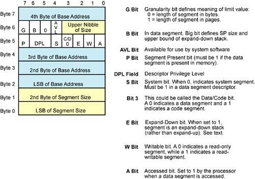
Table 7-1 on page 126 and Table 7-2 on page 127 define the various types of non-system segments. Note that the definition of bits [2:0] is different for code segments and for data/stack segments.
| Type Field Bits | Description | |||
|---|---|---|---|---|
| 3 | 2 | 1 | 0 | |
| C/D | E | W | A | Data/Stack Segment Attributes & Access History |
| 0 | 0 | 0 | 0 | Not yet accessed (A = 0), read-only (W = 0), data segment (stack segment must be read/writable). |
| 0 | 0 | 0 | 1 | Accessed (A = 1), read-only (W = 0), data segment (stack segment must be read/writable). |
| 0 | 0 | 1 | 0 | Not yet accessed (A = 0), read/write (W = 1), and it's either an expand-up stack segment (E = 0) or a data segment. |
| 0 | 0 | 1 | 1 | Accessed (A = 1), read/write (W = 1), and it's either an expand-up stack segment (E = 0) or a data segment. |
| 0 | 1 | 0 | 0 | Not yet accessed (A = 0), read-only (W = 0), data segment (stack segment must be read/writable). |
| 0 | 1 | 0 | 1 | Accessed (A = 1), read-only (W = 0), data segment (stack segment must be read/writable). |
| 0 | 1 | 1 | 0 | Not yet accessed (A = 0), read/write (W = 1), and it's either an expand-down stack segment (E = 1) or a data segment. |
| 0 | 1 | 1 | 1 | Accessed (A = 1), read/write (W = 1), and it's either an expand-down stack segment (E = 1) or a data segment. |
| Type Field Bits | Description | |||
|---|---|---|---|---|
| 3 | 2 | 1 | 0 | |
| C/D | E | W | A | Code Segment Attributes & Access History |
| 1 | 0 | 0 | 0 | Not yet accessed (A = 0), accessible for instruction fetch only (R = 0), non-conforming (C = 0). |
| 1 | 0 | 0 | 1 | Accessed (A = 1), accessible for instruction fetch only (R = 0), non-conforming (C = 0). |
| 1 | 0 | 1 | 0 | Not yet accessed (A = 0), accessible for instruction fetch and for data reads (R = 1), non-conforming (C = 0). |
| 1 | 0 | 1 | 1 | Accessed (A = 1), accessible for instruction fetch and for data reads (R = 1), non-conforming (C = 0). |
| 1 | 1 | 0 | 0 | Not yet accessed (A = 0), accessible for instruction fetch only (R = 0), conforming (C = 1). |
| 1 | 1 | 0 | 1 | Accessed (A = 1), accessible for instruction fetch only (R = 0), conforming (C = 1). |
| 1 | 1 | 1 | 0 | Not yet accessed (A = 0), accessible for instruction fetch and data reads (R = 1), conforming (C = 1). |
| 1 | 1 | 1 | 1 | Accessed (A = 1), accessible for instruction fetch and data reads (R = 1), conforming (C = 1). |
Stack segments must be designated as read/write. The subject of expand-up versus expand-down stacks is covered under the heading “Selecting and Accessing a Stack Segment” on page 161.
The subject of conforming versus non-conforming code segments is covered under the heading “Conforming and Non-Conforming Code Segments” on page 141. Code segments that are marked accessible for instruction fetch and data reads in Table 7-2 may, in addition to instruction fetches, be read using data access instructions (e.g., MOV instructions). This would be necessary if the code segment contains data constants that would need to be read as data (using data access instructions).
Segment Present Bit
The state of this bit indicates whether the code segment or data/stack segment is currently in memory:
P = 1 indicates that the segment of information is present in memory starting at the base address indicated in this descriptor.
P = 0 indicates that the segment of information is not present in memory. Bytes zero through four, six, and seven may be used by the OS (e.g., to store a mass storage address). Byte five is still the attribute byte and defines the privilege level and segment type.
Descriptor Privilege Level (DPL) Field
This two bit field defines the segment's privilege level. Generally speaking, the processor only permits a program to access this segment if the program's privilege level (CPL) meets or exceeds the descriptor's privilege level (DPL). A detailed description of privilege checking can be found in “Code Segments” on page 133 and“Data and Stack Segments” on page 157.
System Bit
A segment descriptor with S = 0 defines a special segment used by the OS. System segments are defined in detail in later sections of this book. Table 7-3 on page 130 identifies the system segment types.
Available Bit
This bit is not used by the processor and can be used by the OS to describe an additional, OS-specific segment attribute.