
Paging Enhancements
PAE-36 Mode
The Problem
Refer to Figure 24-1 on page 555. When any IA32 processor is using the 386 compatible Paging mechanism (described in “386 Demand Mode Paging” on page 209), a 2-level lookup is performed to translate the 32-bit linear address into the 32-bit physical memory address. The linear memory address to be accessed is, by definition, a 32-bit address identifying the target location to be accessed within the currently executing task's 4GB virtual memory address space. The 2-level lookup selects a PTE and, assuming that the PTE's Present bit = 1, the PTE's upper 20 bits supplies the upper 20 bits of the 32-bit physical memory address that will be accessed. The lower 12 bits of the linear address is also used as the lower 12 bits of the physical address.
Figure 24-1. 386-Compatible Paging Address Translation
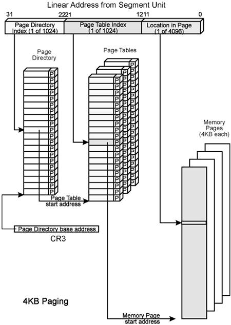
Since the resulting physical memory address is only 32 bits wide, the 32-bit virtual memory address can only be mapped to a location in the lower 4GB of physical memory address space. There is no way to map the supplied 32-bit virtual memory address to a physical memory location above the 4GB address boundary.
The Pentium® Pro, Pentium® II, Pentium® III, Pentium® 4 and all Xeon processors implement external address pins A[35:3]#, permitting the processor to address a total of 64GB of physical memory (note that the Celeron and Pentium® M processors only implement address pins A[31:3]# and are therefore limited to addressing the lower 4GB of physical memory). When an IA32 processor is using the 386-compatible Paging mechanism, however, it is not capable of asserting address pins A[35:32]#.
The Solution: PAE-36 Mode
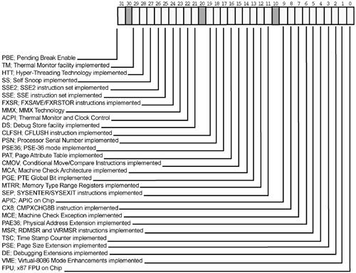
With the advent of the Pentium® Pro processor, a new feature was introduced that permits the supplied 32-bit virtual memory address to be mapped to a physical memory location that is either below or above the 4GB address boundary anywhere within the 64GB addressable address space. This feature is referred to as PAE-36 Mode (Physical Address Extension 36-bit). This section provides a detailed description of PAE-36 Mode. A processor's support for this feature may be determined by executing a CPUID request type 1 and checking EDX[PAE] (1 indicates it is supported; see Figure 24-23 on page 591). Starting with the Pentium® Pro, it is supported by all subsequent IA32 processors.
Enabling PAE-36 Mode
PAE-36 Mode is enabled by setting CR4[PAE] = 1 (see Figure 24-2 on page 556). Note that the processor must also be operating in Protected Mode—CR0[PE] = 1, with Paging enabled—CR0[PG] = 1.

The Application Is Still Limited to a 4GB Virtual Address Space
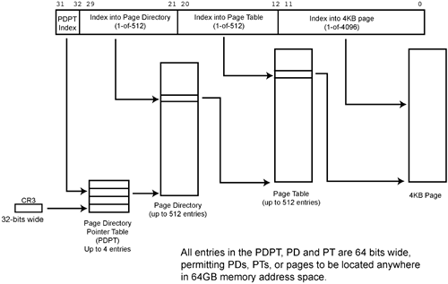
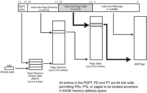
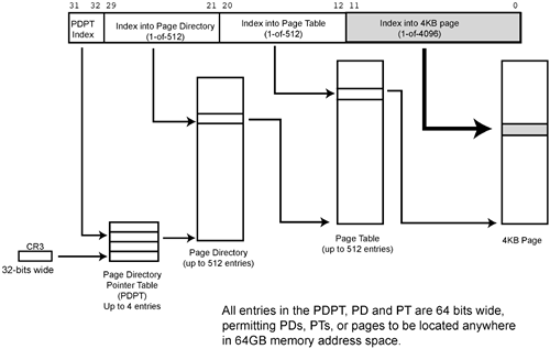
The currently executing program is still limited to a 32-bit (i.e., 4GB) virtual address space consisting of a total of 1M (220) 4KB pages, but the Paging Unit can now map (i.e., translate) the specified 32-bit linear address to a destination physical page anywhere in a 64GB (rather than 4GB) physical address space. The translation is performed by using a 3-level, rather than a 2-level, directory lookup.
The OS Creates the Application's Address Translation Tables
Just as with the 386-compatible mechanism, the OS builds the paging-related tables in system memory and places the base address of the top level directory in CR3 (see Figure 24-3 on page 557). The top level directory is referred to as the Page Directory Pointer Table (PDPT).
CR3 Is Loaded with the Top Level Address Translation Table Pointer
Whenever a task switch occurs, the processor loads CR3 (see Figure 24-4 on page 558) with the pointer to the top level address translation table associated with the current task. CR3[31:5] specifies the upper 27 bits of the PDPT's 32-byte aligned physical base address. The processor assumes that the lower five bits of the address are zeros, thereby forcing the base address to be aligned on an address boundary evenly divisible by 32.
Figure 24-4. CR3 Format With PAE-36 Mode Enabled

The OS uses CR3[PWT] and CR3[PCD] to tell the processor whether or not the PDPT entries can be cached and, if they can, whether to treat the area of memory containing the table as cacheable write-through or cacheable write back memory. See Table 24-1 on page 558.
| PCD | PWT | Memory Type |
|---|---|---|
| 0 | 0 | The processor is permitted to cache entries from the table pointed to by this entry and treats the area of memory containing the table as cacheable write back (WB) memory wherein table entries in the cache can be in the M, E, S or I state. |
| 0 | 1 | The processor is permitted to cache entries from the table pointed to by this entry and treats the area of memory containing the table as cacheable write through (WT) memory wherein table entries in the cache can be in the S or I state. |
| 1 | na | The processor is not permitted to cache entries from the PDPT. |
| 1 | na |
The Page Directory Pointer Table Lookup
When the 32-bit linear address is submitted to the Paging Unit for a lookup, the address translation is performed. Refer to Figure 24-3 on page 557. The upper two bits of the address (bits [31:30]) select one of the four entries in the PDPT. The selected PDPT entry (PDPTE) is 64 bits wide and has the format shown in Figure 24-5 on page 559. Bit 0 is the Present bit:
PDPTE[P] = 0: The Page Directory (the second level directory) is not present in memory. Selection of this PDPTE causes the processor to experience a Page Fault exception. The other bits in the selected PDPTE are ignored.
PDPTE[P] = 1: The Page Directory (the second level directory) is present in memory. PDPTE[35:12] contains the upper 24 bits of the Page Directory's 4KB-aligned 36-bit physical base address and PDPTE[PCD] and PDPTE[PWT] specify what caching policy the processor must use when accessing the Page Directory (see Table 24-1 on page 558). The Page Directory base address can be anywhere in the 64GB memory address space.

The Page Directory Lookup
Refer to Figure 24-6 on page 560. Linear address bits [29:21] select 1-of-512 entries (PDEs) in the selected Page Directory. If the Present bit in the PDE = 0, the entry is not valid and the PD is not currently in memory. This causes the processor to experience a Page Fault exception. If the Present bit in the selected PDE = 1 however, then the entry is valid and contains either the base address of a Page Table (PT) or the base address of a 2MB page in physical memory. Assuming that the selected PDE is valid (i.e., PDE[P] = 1), the PDE has one of the two formats described in the next two sections.
Figure 24-6. Linear Address Bits [29:21] Select a PDE in the Selected Page Directory

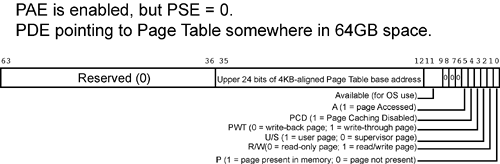
PDE Points to a Page Table
If PDE[PS] = 0, the PDE contains the upper 24 bits of the 4KB-aligned base address of a Page Table (PT). In this case, the PDE format is the one shown in Figure 24-7 on page 561 and consists of the following bit fields:
- -
P.
If the Present bit = 1, then the PDE is valid and contains the start address and attributes of a Page Table in memory. If the P bit = 0, the processor generates a Page Fault exception.
- -
PT base address.
This field contains the upper 24 bits of the 36-bit, 4KB-aligned base address of a Page Table in memory.
- -
R/W.
This bit indicates whether the PT is read-only or read/writable.
- -
U/S.
This bit indicates whether access is restricted to privilege level 0, 1 or 2 code or not.
- -
PWT and PCD.
These two bits indicate the cacheability of the PT (see Table 24-1 on page 558).
- -
Accessed.
The processor automatically sets this bit to one the first time the PT is accessed.
- -
Available.
These three bits are available to the OS to assign additional, OS-specific attributes to the PT.
The final step in the address translation is described in “The Page Table Lookup” on page 563.
PDE Points to a 2MB Physical Page
If the selected PDE's PDE[PS] = 1, the PDE contains the 2MB-aligned base address of a 2MB page in physical memory (see Figure 24-8 on page 562). In this case, no third level lookup is performed and the address translation is complete. The final 36-bit physical memory address is constructed as follows:
- The upper 15 bits of the physical memory address is supplied by PDE[35:21] and
- the lower 21 bits is supplied by linear address bits [20:0].
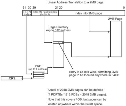
The PDE format is the one shown in Figure 24-9 on page 563:
- -
P.
If the Present bit = 1, then the PDE is valid and contains the start address and attributes of the targeted 2MB physical page in memory. If the P bit = 0, the processor generates a Page Fault exception.
- -
Target 2MB-aligned physical page base address.
This field contains the upper 15 bits of the 36-bit, 2MB-aligned base address of the target 2MB physical page anywhere in the 64GB memory space.
- -
R/W.
This bit indicates whether the target page is read-only or read/writable.
- -
U/S.
This bit indicates whether access to the page is restricted to privilege level 0, 1, or 2 code or not.
- -
PWT and PCD.
These two bits indicate the cacheability of the page (see Table 24-1 on page 558).
- -
Accessed.
The processor automatically sets this bit to one the first time the page is accessed.
- -
Dirty.
The processor automatically sets this bit to one the first time any location in the 2MB page is written to.
- -
Global.
If this bit is set to one, the 2MB page is used by multiple tasks. For a detailed description, refer to “Global Pages” on page 567.
- -
Available.
These three bits are available to the OS to assign additional, OS-specific attributes to the page.

The Page Table Lookup
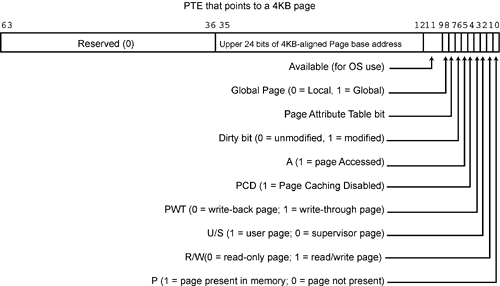
If the selected PDE is valid (i.e., PDE[P] = 1) and PDE[PS] = 0, then the PDE (see Figure 24-7 on page 561) points to the third and final lookup table, the Page Table. As illustrated in Figure 24-10 on page 564, the Paging Unit uses linear address bits [20:12] to index into the selected Page Table. The PTE selected by the index value has the format shown in Figure 24-12 on page 566:
P. If the Present bit = 1, then the PTE is valid and contains the start address and attributes of the targeted physical page in memory. If the P bit = 0, the processor generates a Page Fault exception.
Target 4KB-aligned physical page base address. This field contains the upper 24 bits of the 36-bit, 4KB-aligned base address of the target 4KB physical page anywhere in the 64GB memory space.
R/W. This bit indicates whether the target page is read-only or read/writable.
U/S. This bit indicates whether access to the page is restricted to privilege level 0, 1, or 2 code or not.
PWT and PCD. These two bits indicate the cacheability of the page (see Table 24-1 on page 558).
Accessed. The processor automatically sets this bit to one the first time the page is accessed.
Dirty. The processor automatically sets this bit to one the first time any location in the 4KB page is written to.
Global. If this bit is set to one, the 4KB page is used by multiple tasks. For a detailed description, refer to “Global Pages” on page 567.
Available. These three bits are available to the OS to assign additional, OS-specific attributes to the page.
Figure 24-10. Linear Address Bits [20:12] Select a PTE in the Selected Page Table
The address translation is complete. The final, 36-bit physical memory address is constructed as follows (see Figure 24-11 on page 565):
The upper 24 bits of the physical memory address is supplied by PTE[35:12] and
the lower 12 bits are supplied by linear address bits [11:0].
Figure 24-11. Linear Address Bits [11:0] Select the Target Location in the Physical Page
Windows OS PAE Support
Refer to Table 24-2 on page 566. With PAE enabled (the default is disabled; it is enabled by adding the /PAE switch statement to the OS boot.ini file), Windows will assign no more than 2GB to each task. If more memory is needed for a task, the /3GB switch can be added to the OS's boot.ini file of Windows 2000, Windows .NET Enterprise Server and Datacenter Server.
| Windows OS Version | PAE Supported? | Comments |
|---|---|---|
| Windows 2000 Server | No | The OS limits the total amount of addressable physical memory to 4GB. |
| Windows 2000 Advanced Server | Yes | When PAE is enabled (the default is disabled), the OS limits the total amount of addressable physical memory to 8GB. |
| Windows 2000 Datacenter Server | Yes | When PAE is enabled (the default is disabled), the OS limits the total amount of addressable physical memory to 32GB. |
| Windows .NET Web Server | No | The OS limits the total amount of addressable physical memory to 2GB. |
| Windows .NET Standard | No | The OS limits the total amount of addressable physical memory to 4GB. |
| Windows .NET Enterprise | Yes | When PAE is enabled (the default is disabled), the OS limits the total amount of addressable physical memory to 32GB. |
| Windows .NET Datacenter | Yes | When PAE is enabled (the default is disabled), the total amount of addressable physical memory is 64GB. |
Linux PAE Support
The Linux 2.4 kernel was the first Linux kernel to support PAE-36 Mode. The OS permits up to 3GB of memory to be allocated for each task and reserves 1GB of memory space for the OS kernel.
Global Pages
Problem
When a task switch occurs, a new value is loaded in CR3 from the new task's TSS. This selects the set of page address translation tables associated with the new task. The processor automatically deletes all PTEs (and 2MB or 4MB PDEs) currently cached in the TLB (because they were cached from the address translation tables associated with the previous task). The TLB misses that occur after a task switch occurs negatively affects performance at the start of the new task.
Global Page Feature
The Pentium® Pro processor introduced the Global Page feature (and it is supported by all subsequent IA32 processors). A processor's support for this feature may be determined by executing a CPUID request type 1 and checking EDX[PGE] (1 indicates it is supported; see Figure 24-23 on page 591). It is enabled by setting CR4[PGE] = 1 (see Figure 24-13 on page 568).

The OS can designate one or more pages as being global to multiple tasks by setting:
(with PAE disabled and a 4KB page) the 4KB page's PTE[G] bit = 1 (see Figure 24-14 on page 569).
Figure 24-14. PTE Format

(with PAE disabled and a 4MB page) the 4MB pages's PDE[G] bit = 1 (see Figure 21-9 on page 503).
(with PAE enabled and a 4KB page) the 4KB page's PTE[G] bit = 1 (see Figure 24-12 on page 566).
(with PAE enabled and a 2MB page) the PDE[G] bit = 1 (see Figure 24-9 on page 563).
Whenever a task switch occurs and CR3 is loaded with the address of the top level directory for the new task, the processor purges all PTEs from the TLB with the exception of those that are marked as global pages. The PTEs and PDEs for global pages are retained. The Intel® documentation says the global PTEs are retained in the TLB for an indeterminate period of time. In fact, they are retained until the TLB's LRU algorithm causes a global PTE to be cast out to make room for a new PTE.