Finding the Location of a Physical Page
Find the Page Table First
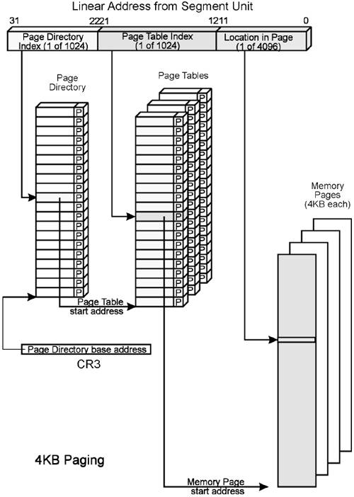
Refer to Figure 12-6 on page 223 during the following discussion. When the 32- bit linear address is supplied to the Paging Unit by the segment unit, the upper ten bits, [31:22], identify the target page group. The 10-bit group number is used to index into the Page Directory, selecting 1 of up to 1024d Page Tables. Since each Page Directory Entry (PDE) is four bytes long, the Paging Unit multiplies the index by four to create the offset into the Page Directory. It then adds the resulting offset to the Page Directory Base Address (from CR3) to create the start address of the PDE in physical memory. The entry is read from memory and the Page Table Present bit (bit zero) is tested to determine if the target Page Table is present in memory.
Figure 12-6. Page Table Lookup Mechanism
When the Target Page Table Is in Memory
The Paging Unit interprets the PDE as illustrated in Figure 12-7 on page 225. Table 12-1 on page 224 describes each element of the PDE. P = 1 indicates that the selected Page Table is in memory, and that the selected PDE contains the upper 20 bits of the 4KB-aligned physical base address of the Page Table in bits [31:12].
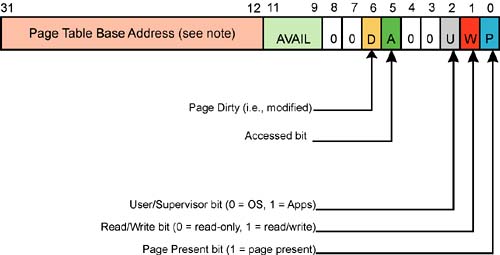
If P = 0, the Page Table is not present in memory. The actions taken by the Paging Unit are covered in the section entitled “When the Target Page Table Isn't in Memory” on page 225.
Assuming that the Page Table is in memory, the Paging Unit must access it to discover the location of the target physical page that this virtual page address is mapped to. This topic is covered in the section entitled “Find the Page Using an Entry in a Page Table” on page 229.
When the Target Page Table Isn't in Memory
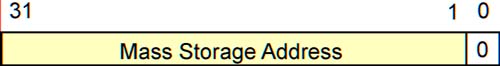
If P = 0 in the selected PDE, the target Page Table isn't currently in memory. This results in a Page Fault exception. The return address pushed onto the stack points to the instruction that submitted the 32-bit linear address to the Paging Unit. The processor latches the linear address into CR2, the Page Fault Address register (see Figure 12-11 on page 229), so that it may be examined by the OS's Page Fault exception handler. The actions taken are illustrated in Figure 12-8 on page 226 through Figure 12-10 on page 228.
Figure 12-11. Page Fault Register (CR2)
![]()
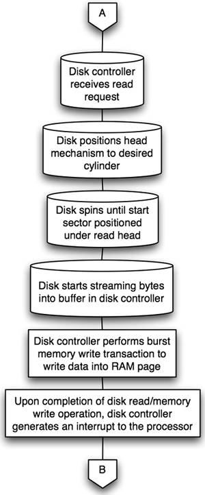
Figure 12-8. Page Table Not in Memory (1-of-3)
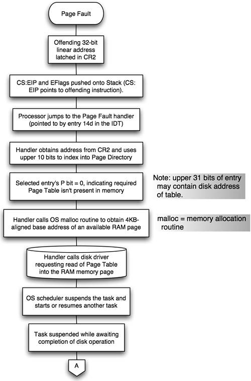
Figure 12-10. Page Table Not in Memory (3-of-3)

Now that the proper Page Table has been located in memory, the Paging Unit must access it to discover the location of the target physical page. This topic is covered in the next section.
Figure 12-9. Page Table Not in Memory (2-of-3)

Figure 12-12. PDE or PTE when Page Table (or page) not Present in Memory
Find the Page Using an Entry in a Page Table
Now that the correct Page Table has been located (see “Find the Page Table First” on page 222), the table must be accessed to obtain the location of the physical page that the linear page is mapped to. The base address of the Page Table was obtained from the PDE (see Figure 12-7 on page 225). The middle 10 bits of the linear address identifies the page (1-of-1024d) within the page group and the corresponding Page Table Entry (PTE) in the selected Page Table. The processor's Paging Unit indexes into the selected Page Table by multiplying the 10-bit page number by four (because there are four bytes per entry). The resulting offset is added to the table's base address to obtain the start physical memory address of the PTE for the target page. Figure 12-13 on page 230 illustrates the Page Table entry associated with a page. The Paging Unit checks the P bit (page Present) to determine if the physical page is currently in memory. The two sections that follow describe the actions taken when the page is in memory versus when it's not in memory.

When the Target Page Is in Memory
When P = 1, the target physical page is in memory. It starts at the 4KB-aligned base address indicated in the PTE's base address field. The Paging Unit creates the exact 32-bit address of the physical location in the page as follows:
The upper 20 bits are obtained from the PTE's base address field.
The lower 12 bits are supplied directly by the lower 12 bits of the 32-bit linear address.
This 32-bit address is the address used in the resultant FSB memory transaction.
When the Target Page Isn't in Memory
If P = 0 in the selected PTE, the target page isn't currently in memory, resulting in a Page Fault exception. The return address pushed onto the stack points to the instruction that submitted the 32-bit linear address to the Paging Unit. The processor latches the linear address into CR2, the Page Fault Address register (see Figure 12-11 on page 229), so that it may be examined by the OS's Page Fault exception handler. The actions taken are illustrated in Figure 12-14 on page 231 through Figure 12-16 on page 233.
Figure 12-14. Page Not in Memory (1-of-3)
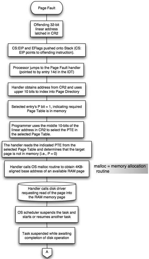
Figure 12-16. Page Not in Memory (3-of-3)
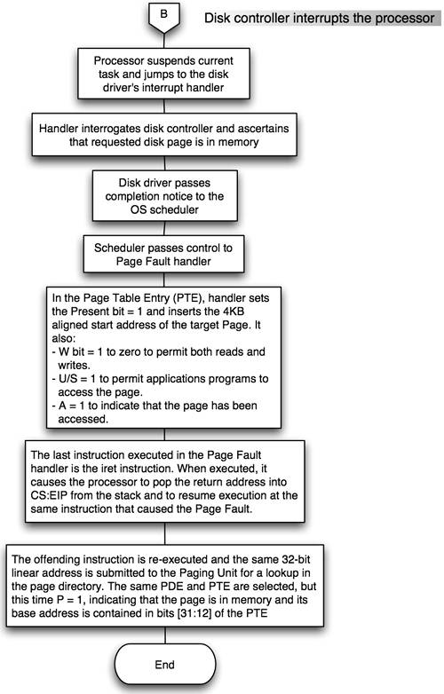
Figure 12-15. Page Not in Memory (2-of-3)